
Reverse dispersion optical fiber and optical transmission line using reverse dispersion optical fiber

a reverse dispersion, optical fiber technology, applied in the direction of optical fiber with multi-layer core/cladding, optical waveguide light guide, instruments, etc., can solve the problem of increasing the bending loss or dispersion slope, the non-linearity of optical fiber due to the interaction between the plurality of signal wavelengths, and the increase of the output of optical signals. problem, to achieve the effect of increasing the effective core area and reducing waveform distortion

Inactive Publication Date: 2005-04-12
FURUKAWA ELECTRIC CO LTD
View PDF5 Cites 5 Cited by
  • Summary
  • Abstract
  • Description
  • Claims
  • Application Information

AI Technical Summary

Benefits of technology

An object of the present invention is to provide a reverse dispersion optical fiber reduced in waveform distortion due to non-linearity by increasing the effective core area.
Another object of the present invention is to provide an optical transmission line reduced in waveform distortion using such a reverse dispersion optical fiber.

Problems solved by technology

In wavelength division multiplex transmission, however, the non-linearity in optical fiber due to the higher output of optical signals and to the interaction between the plurality of signal wavelengths has arisen as a new problem.
Among the non-linearity phenomena, the waveform distortion caused by self-phase modulation (SPM) or cross-phase modulation (XPM) is becoming a major problem.
If the effective core area increases in a non-zero dispersion shift fiber, however, in general the bending loss or dispersion slope increase, so in practice the increase in the effective core area has been restricted.
Four-wave mixing (FWM), another non-linearity phenomenon, becomes remarkable when the dispersion is small, so an optical fiber with a small dispersion such as a non-zero dispersion shift fiber is disadvantageous in that point.

Method used


Image

  • Reverse dispersion optical fiber and optical transmission line using reverse dispersion optical fiber
  • Reverse dispersion optical fiber and optical transmission line using reverse dispersion optical fiber
  • Reverse dispersion optical fiber and optical transmission line using reverse dispersion optical fiber

Examples


examples

The efficacy of the reverse dispersion optical fiber of the above embodiment was confirmed by the examples shown below.

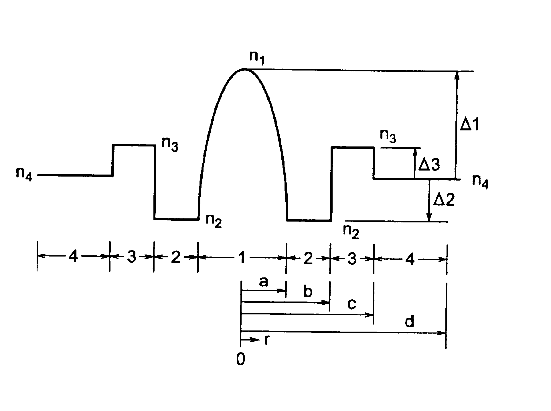
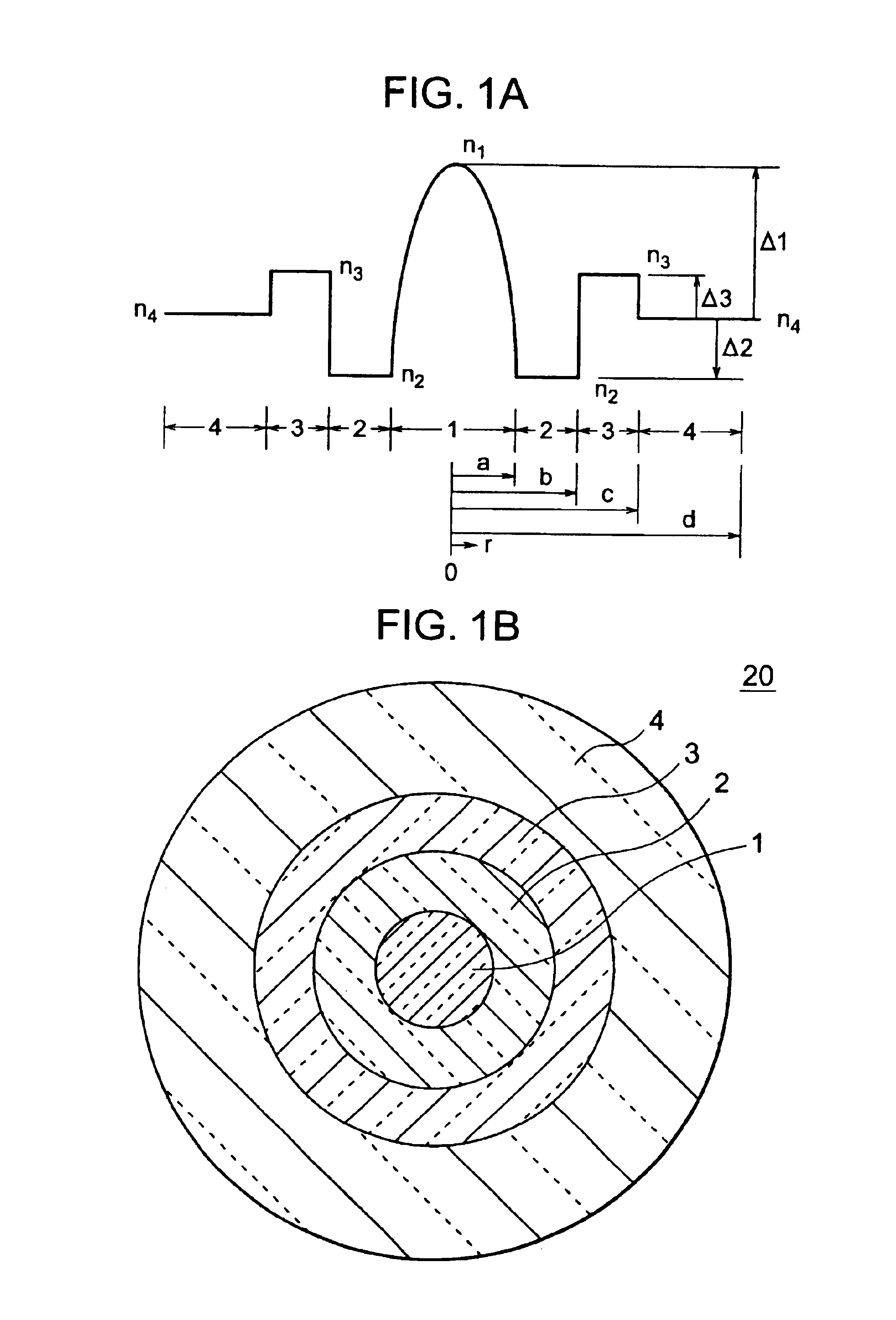
Reverse dispersion optical fibers of the present embodiment were fabricated using optical fibers of the refractive index profile “W+segment core” shown in FIGS. 1A and 1B and aiming at reverse dispersion optical fibers of Simulation Nos. 3 and 7 of Table 1 having refractive index distribution coefficients α about 10 so as to obtain low non-linearity reverse dispersion optical fibers.

Table 2 shows the optical transmission characteristics at the wavelength 1550 nm of Examples 1 and 2.

Table 2 also shows a typical positive dispersion optical fiber, that is, a cutoff shifted fiber (CSF), and reverse dispersion optical fibers of Comparative Examples 1 and 2.

TABLE 2Disper-Bend-Trans.sionSlopeingPMDAeffloss(ps / nm / (ps / nm2 / λcloss(ps / (μm2)(dB / km)km)km)(nm)(dB / m)km1 / 2)CSF85.00.190 18.00.06015002.00.04Comp.24.00.240−24.0−0.065  82010.0 0.07Ex. 1Comp.21.00.260−40.0−0.130  8205.00...


PUM


Abstract

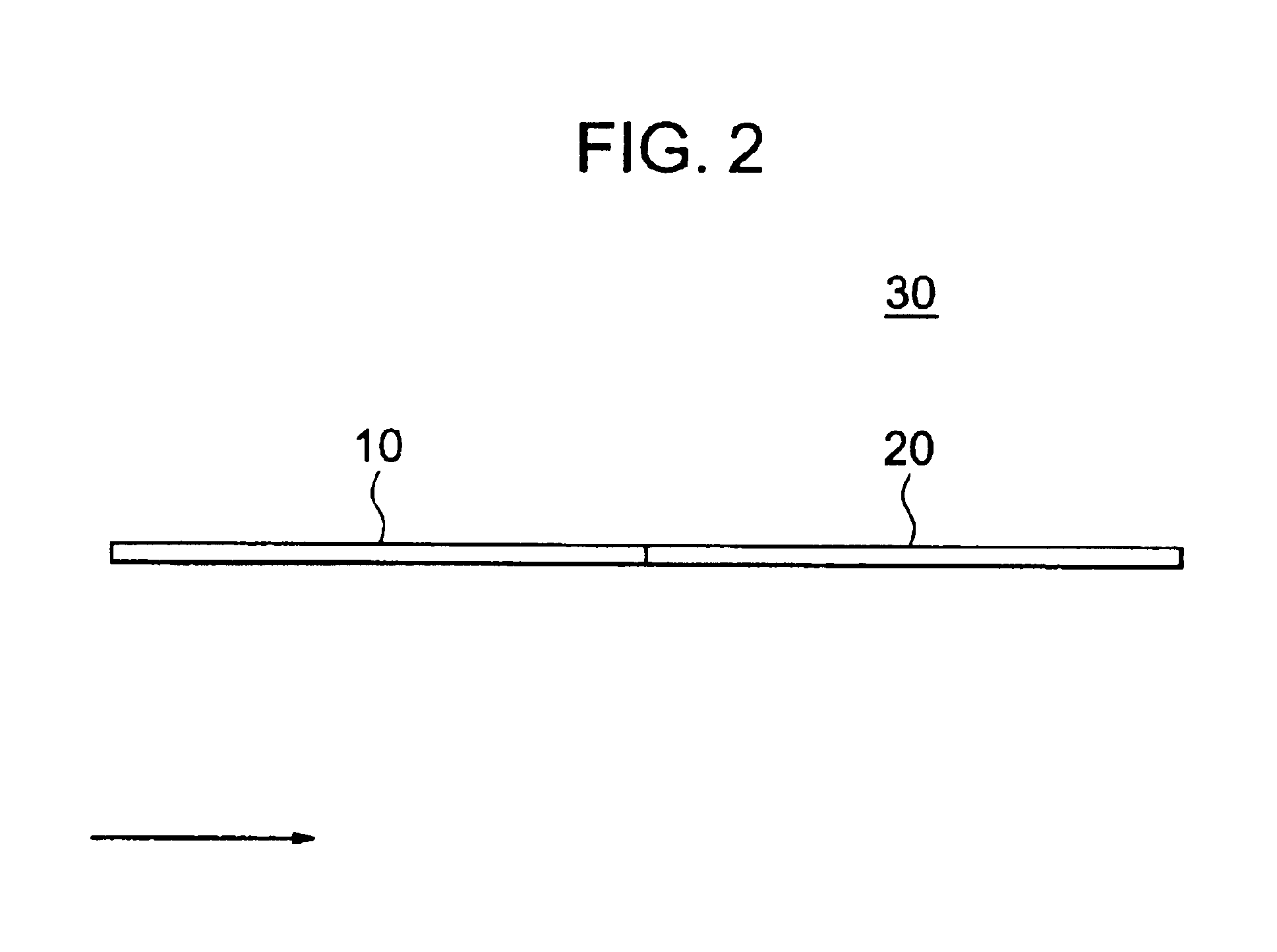
A reverse dispersion optical fiber having a small waveform distortion caused by non-linearity wherein an effective core area is made at least 50 μm2 and a dispersion at a wavelength of the 1.55 μm band is made not more than −10 ps / nm / km and a dispersion management optical transmission line having a small waveform distortion obtained by connecting a positive dispersion optical fiber and that reverse dispersion optical fiber in that order along a direction of signal transmission and having a total dispersion of substantially zero.

Description

BACKGROUND OF THE INVENTION1. Field of the InventionThe present invention relates to an optical fiber and an optical transmission line using an optical fiber, more particularly relates to a reverse dispersion optical fiber having a low non-linearity suitable for wavelength division multiplex (WDM) transmission and an optical transmission line obtained by connecting such a reverse dispersion optical fiber and a positive dispersion optical fiber to reduce the total dispersion.2. Description of the Related ArtWith optical transmission being increased in speed and capacity, WDM transmission technology for transmitting a plurality of optical signals with different wavelengths multiplexed is in the spotlight as a key technology. In wavelength division multiplex transmission, however, the non-linearity in optical fiber due to the higher output of optical signals and to the interaction between the plurality of signal wavelengths has arisen as a new problem.Among the non-linearity phenomena,...

Claims


Application Information

Patent Timeline
Patent Type & Authority Patents(United States)
IPC IPC(8): G02B6/036G02B6/028G02B6/02
CPCG02B6/02009G02B6/02238G02B6/02252G02B6/29377G02B6/0281G02B6/03644G02B6/02285
Inventor MUKASA, KAZUNORI
Owner FURUKAWA ELECTRIC CO LTD
Learn More