

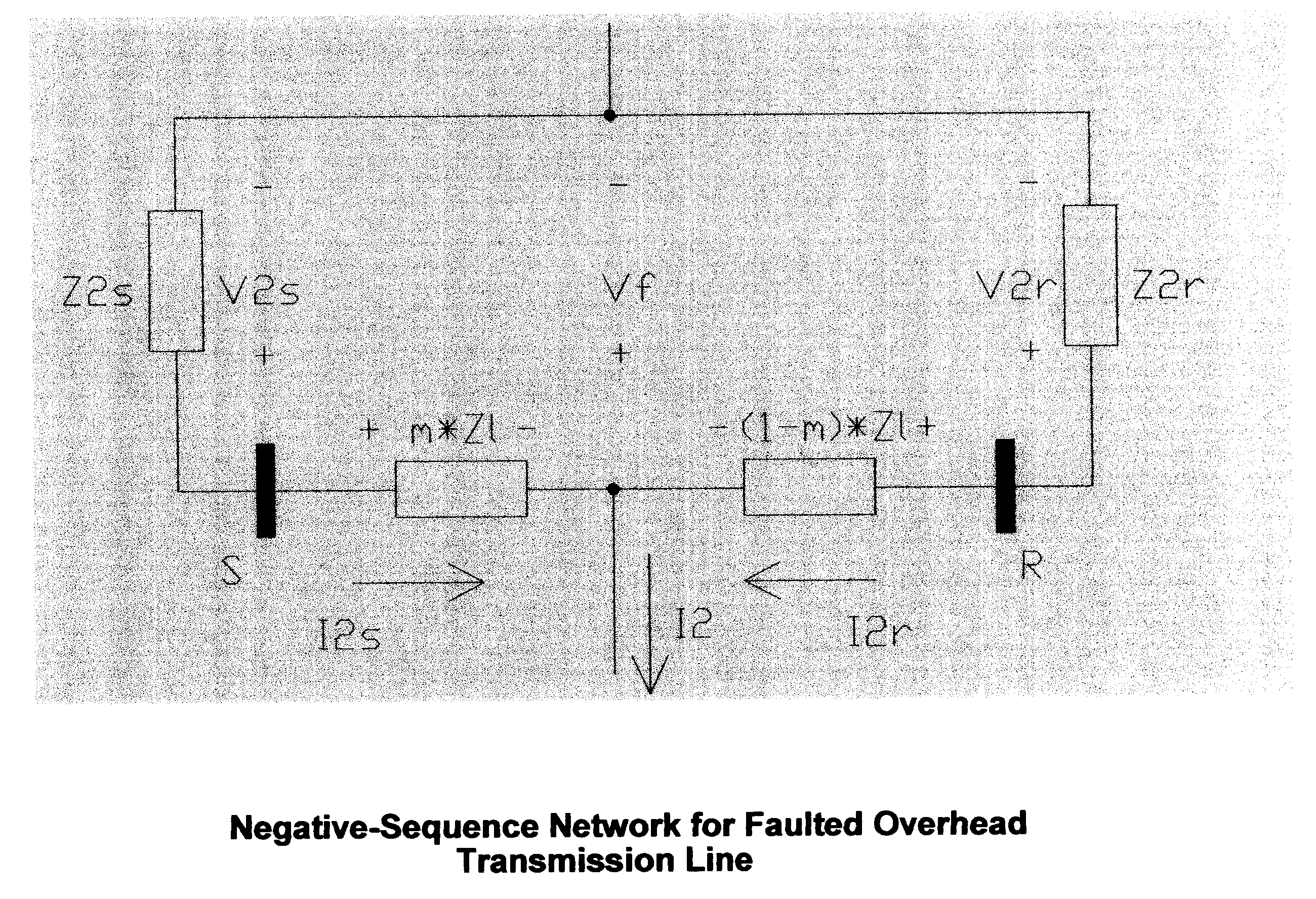
Double-ended distance-to-fault location system using time-synchronized positive-or negative-sequence quantities
a distance-to-fault location and positive-or-negative-sequence technology, applied in noise figure or signal-to-noise ratio measurement, instruments, digital computer details, etc., can solve the problems of heavy current quickly damage to the line conductor and connected equipment, system currently in use, and a lot of time and expense required to patrol the overhead line for possible damag
- Summary
- Abstract
- Description
- Claims
- Application Information
AI Technical Summary
Benefits of technology
Problems solved by technology
Method used
Image

Examples
example i
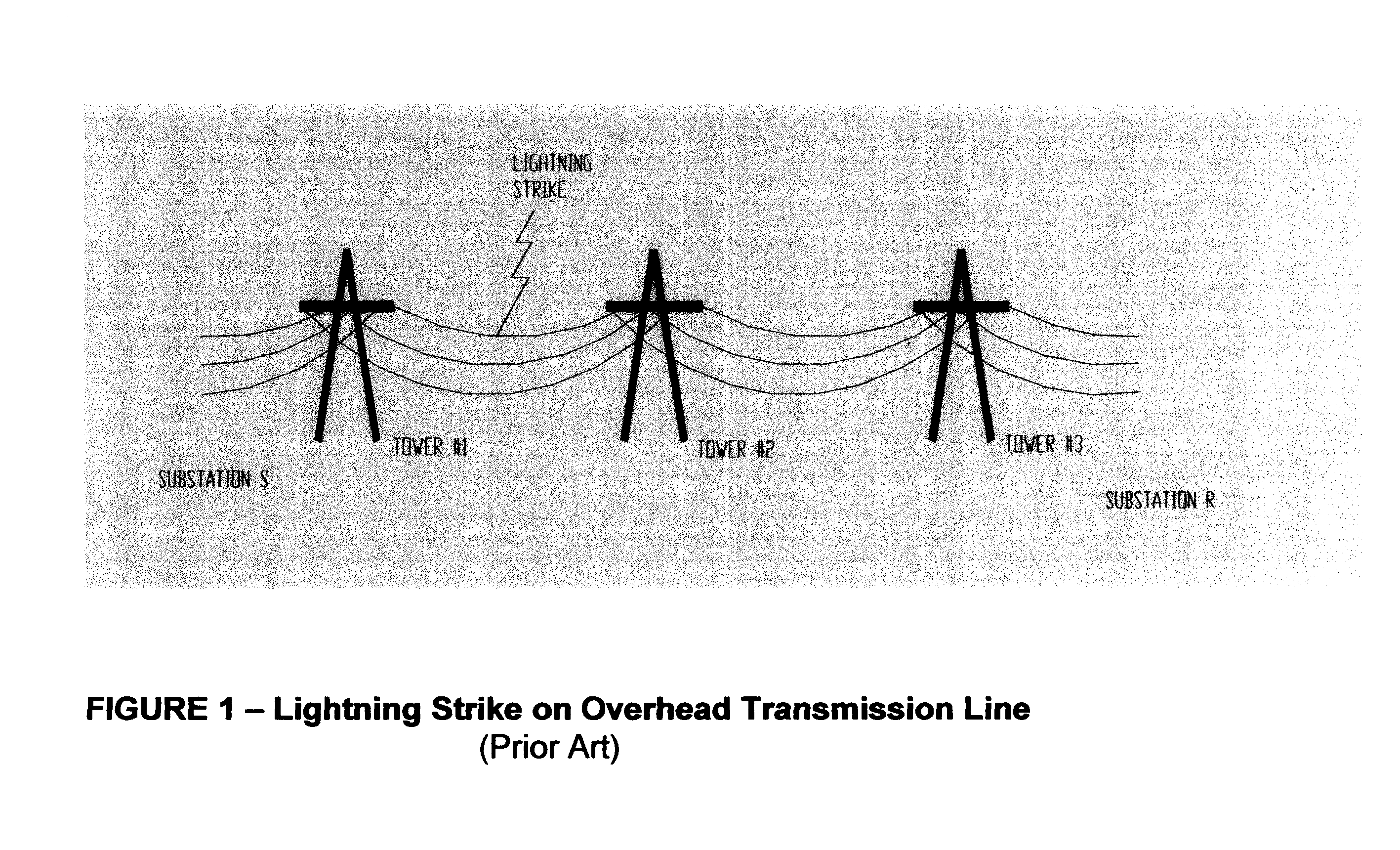
An “A” Phase-to-ground fault occurred on the 230 kV overhead transmission line running from Wilson substation to Greenville substation within the Carolina Power and Light transmission system. Conventional methods proved futile when utility personnel tried to locate the fault.
The fault turned out to be an old oak tree growing under the line. This vegetation represented an extremely high level of fault resistance (that is, many times greater than the impedance of the transmission line).
The double-ended distance-to-fault process of the present invention using time synchronized negative-sequence quantities was applied using the voltage and current recorded by instrumentation at the two ends of the line. The error was less than 5%.
Below are the actual calculations for this case. The subscript ‘S’ represents Greenville and subscript ‘R’ represents Wilson.
V2S=8.454∠238.6° kV
I2S=456.69∠368.4° A
V2R=6.697∠239.4° kV
I2R=345.82∠350.4° A
I2=I2S+I2R=792.82∠0.7° A
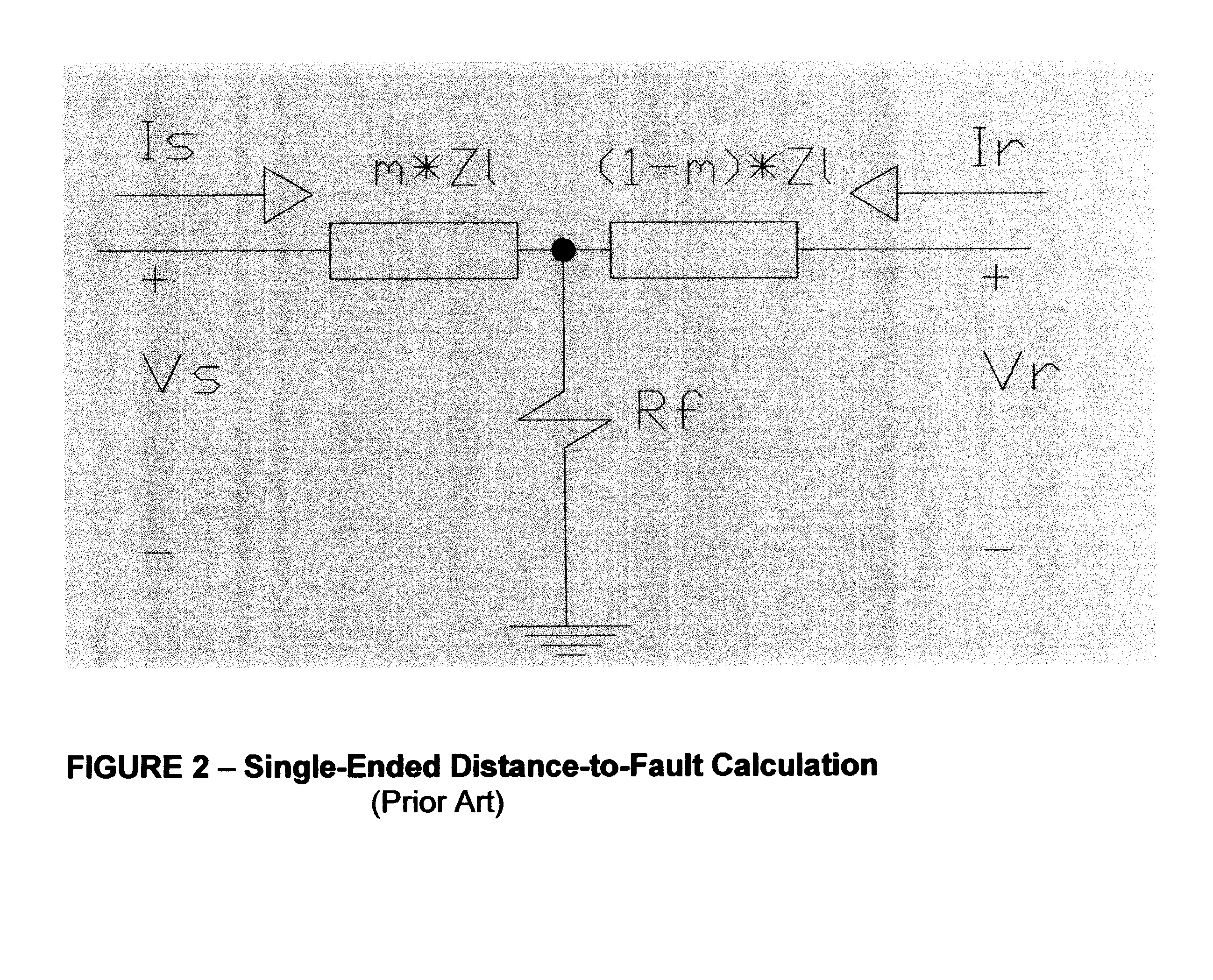
ZL=24.899∠82.7 ∠ primary m=V2 ...
example ii
A “B” Phase-to-“C” Phase fault occurred on the 230 kV overhead transmission line running from Wake substation to Selma substation within the Carolina Power and Light transmission system.
The fault was due to a truck that caught fire under the line. The resulting smoke created a path for electrical current to flow between “B” and “C” Phase conductors.
The double-ended distance-to-fault process of the present invention using time synchronized negative-sequence quantities was applied using the voltage and current recorded by instrumentation at the two ends of the line. The error was less than 2%.
Below are the actual calculations for this case. The subscript ‘S’ represents Wake and subscript ‘R’ represents Selma.
V2S=51.7∠1.9° kV
I2S=11,900∠96.5° A
V2R=37.9∠1.3° kV
I2R=2,470∠94° A
I2=I2S+I2R=14,370∠96° A
ZL=11.96∠85.8°Ω primary
|m|=0.092 per-unit
The actual line length is 21 miles. Therefore, the distance-to-fault with respect to Wake was 1.93 miles. The actual distance-to-fault was 1.5 mi...
PUM
 Abstract
Description
Claims
Application Information