Metal strip for interlocking floorboard and a floorboard using same

a technology of interlocking floorboards and metal strips, which is applied in the direction of building components, structural elements, roof coverings, etc., can solve the problems of undesired joint gaps between boards, poor strength, and certain differences, so as to avoid undesired joint gaps, not impair mechanical connections, and poor strength

Inactive Publication Date: 2005-04-19
VÄLINGE INNOVATION AB
View PDF256 Cites 103 Cited by
  • Summary
  • Abstract
  • Description
  • Claims
  • Application Information

AI Technical Summary

Benefits of technology

[0029]A first advantage of the invention is that it ensures that such dimensional changes of the body and / or the strip do not impair the mechanical connection, since, according to the invention, the mechanical connection between the strip and the board body can be biased and, consequently, can automatically and continuously adjust to every dimensional change of these two components. In this way, it is ensured that the strip is always firmly and securely connected to the board body, so that the relative position of these two components remains correct and unchanged. By the invention, strips which are loose and can be displaced relative to the board body are thus avoided and, consequently, undesired joint gaps and poor strength due to loosely attached strips are eliminated.
[0030]In addition to the above-mentioned environmentally-caused dimensional variations of the finished building board, a variation can also occur in the position of the gripping stud in relation to the board body. This positional variation is due to tolerances in the manufacturing of the gripping stud, especially if its gripping edges are formed by milling. As a result of these tolerances, the position of the gripping edges in relation to the joint edge of the body may vary somewhat (e.g. in the order of ±0.05 mm) from one building board to another. If the strip is positioned in relation to the gripping stud at the time of manufacturing, this positional variation of the gripping edges may result in the strip being positioned incorrectly.
[0031]A second advantage of the invention is that the preforming in combination with reverse bending and biasing compensates for the above-mentioned positional variation of the gripping edge, since an “incorrect” position of the gripping edges can be compensated for by the fact that the gripping elements of the strip can be caused always to strike against the gripping edges during bending and be reverse bent to different extents, depending upon the position of the corresponding gripping edge.
[0032]Generally, in manufacturing, it is desirable to be able to operate within the largest possible tolerances, since this reduces set-up and take-down times, checks, and tool grinding. In the present case, a suitably designed preforming can handle tolerances of e.g. 0.15 mm.
[0033]A third advantage provided by the invention is that, by virtue of being preformed, the gripping elements of the strip can always be moved to the correct position in relation to the bending punches and still strike against and be reverse bent by the gripping stud which is positioned within a certain manufacturing tolerance in relation to the bending punches. This advantage means that even if the relative position between the gripping edges of the body and the bending punches should vary somewhat between different punching operations, this does not have a negative effect on the quality of the mechanical connection between the strip and the board body.
[0034]A further advantage achieved by the invention is that the biasing force applied to the gripping stud by the bent gripping elements of the mechanically attached strip is essentially independent of both the punching force which is applied by means of the bending punches and the length of stroke of the bending punches. The advantage of this is that (i) the bending punches and (ii) other punches required for making the floorboard (such as pre-bending punches, punching machines, etc) can be mounted in one and the same punching tool, which during manufacturing moves to-and-fro with a length of stroke common to all punches and a common pressing power. Specifically, this makes it possible to allow the bending punches, when they are moving in the direction of the strip, to continue a distance past the point in the punching motion at which the fastening of the strip to the board body is completed, enabling the other punches to complete their punching function during a final, inactive motion of the bending punches.

Problems solved by technology

However, there are certain differences compared to the prior art with respect to the geometrical shapes of a gripping stud and a locking element.
Such dimensional changes of the body and / or the metal strip may have a negative impact on the mechanical connection between the body and the strip, and may specifically result in undesired joint gaps between the boards as well as poor strength.
If the strip is positioned in relation to the gripping stud at the time of manufacturing, this positional variation of the gripping edges may result in the strip being positioned incorrectly.
Whereas, if the bending punches had been operating towards the edges of the gripping stud, whose position varies in such a punching direction because of the aforementioned manufacturing tolerances, the pressure on the gripping stud would have varied considerably, with the risk of the gripping stud breaking or the fastening of the strip being loose.

Method used


Image

  • Metal strip for interlocking floorboard and a floorboard using same
  • Metal strip for interlocking floorboard and a floorboard using same
  • Metal strip for interlocking floorboard and a floorboard using same

Examples


Embodiment Construction

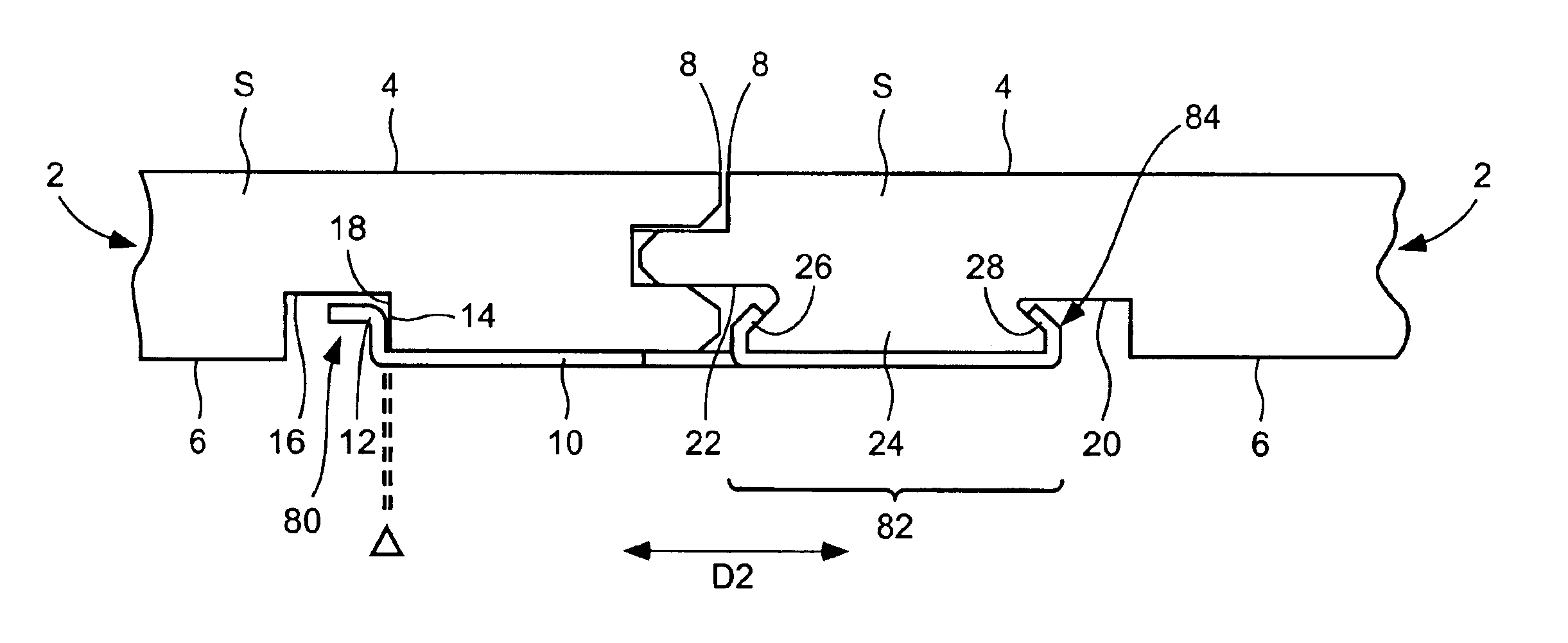
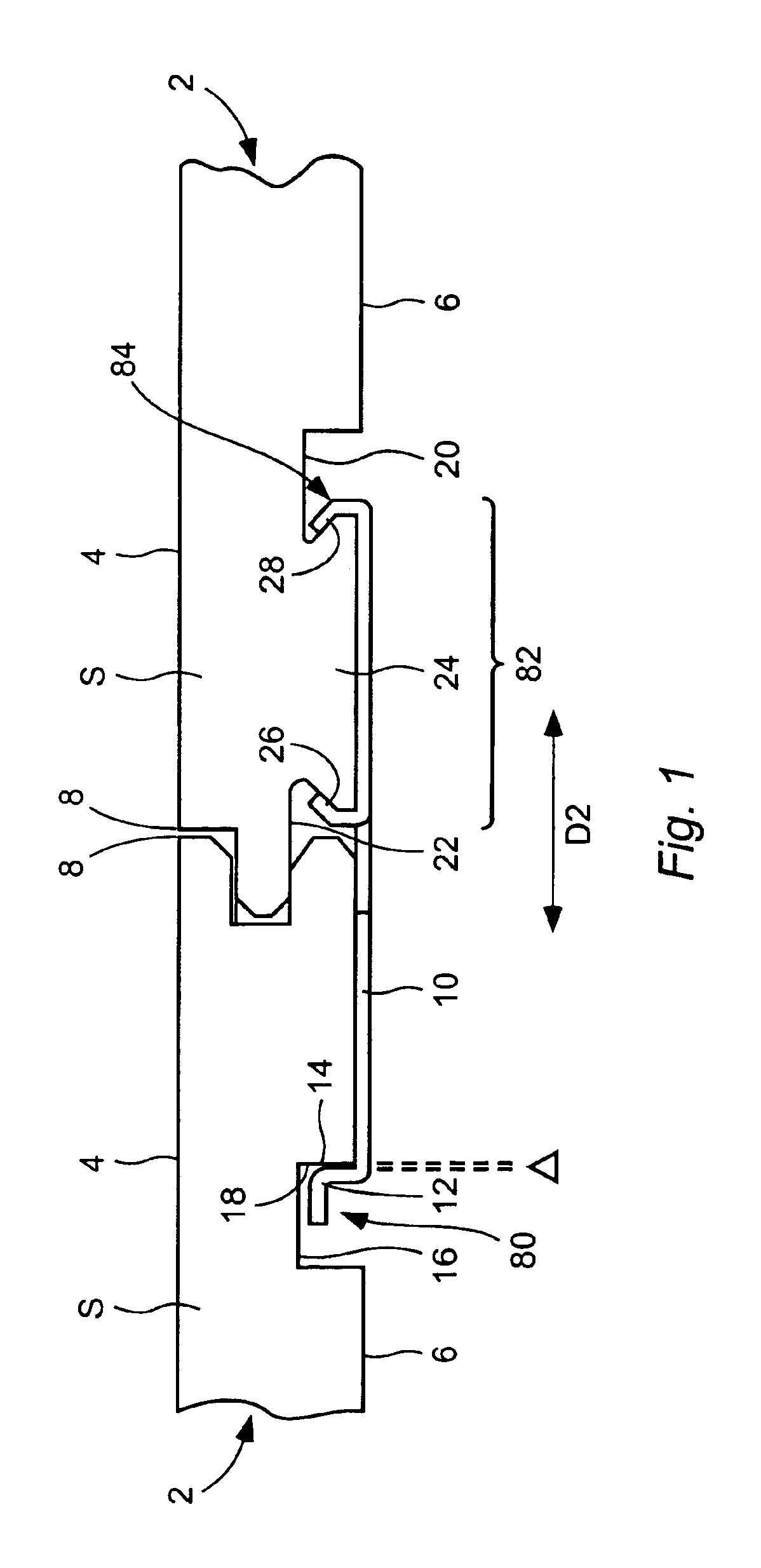
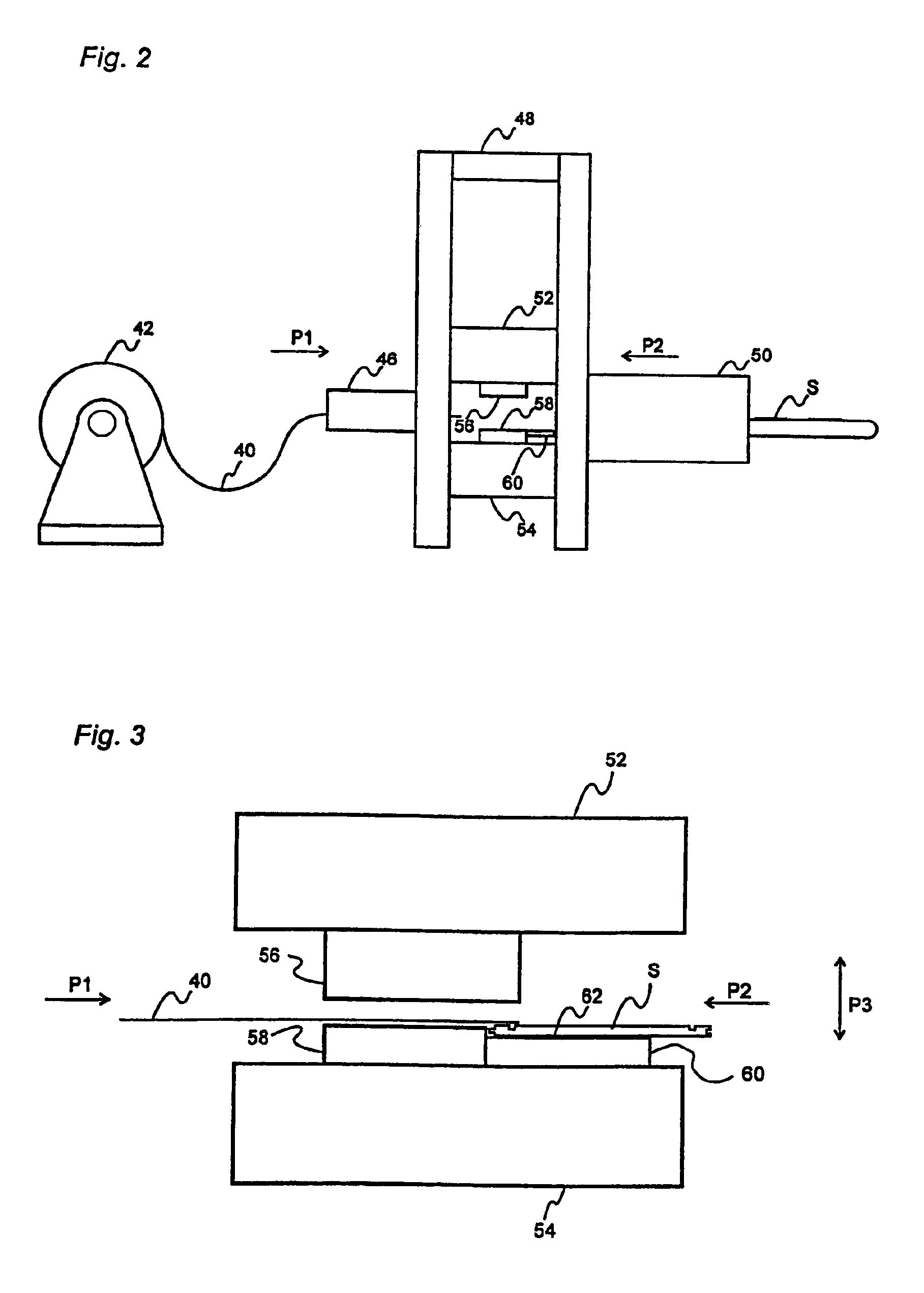
[0045]With reference to FIGS. 2-6 in the appended drawings, a production line will now be described, which is usable for making building boards, such as floorboards, of the type mentioned above with reference to FIG. 1 and in which production line an embodiment of the method according to the invention is implemented. The same reference symbols as in FIG. 1 will be used for the components of the floorboard.

[0046]In FIG. 2, a flexible, formable blank 40, preferably aluminium sheet, is wound onto a reel 42. The aluminium sheet 40 is fed from the reel 42 to a sheet feeder 46. The task of the sheet feeder 46 is gradually to feed (arrow P1) the flat blank 40 into a press 48. On its opposite side, the press 48 (arrow P2) receives machined (milled) bodies S of e.g. compact laminate from a board feeder 50.

[0047]In the production line in FIG. 2, the blank 40 is cut into separate metal strips 10, the locking elements 12 of the strips 10 are formed, and the strips 10 are mechanically attached t...


PUM

PropertyMeasurementUnit
thickaaaaaaaaaa
thickaaaaaaaaaa
angleaaaaaaaaaa

Abstract

The invention relates to a strip for a building board (2), exhibiting a board body (S) which is formed with a gripping stud (24). The strip (10) extends from the body (S) and from which are formed gripping elements (26, 28), which are bent round the gripping stud (24) for mechanical fastening of the strip (10) to the body (S), as well as a locking element (12) for enabling mechanical joining of the board (2) to similar boards.

Description

CROSS-REFERENCE TO RELATED APPLICATIONS[0001]This application is a continuation of application Ser. No. 09 / 816,166, filed on Mar. 26, 2001 now abandoned; which is a continuation of application Ser. No. 09 / 323,999, filed on Jun. 2, 1999, now U.S. Pat. No. 6,205,639; which is a continuation of PCT / SE97 / 02033, which was filed on Dec. 5, 1997; and this application is also a continuation of application Ser. No. 09 / 534,007, filed on Mar. 24, 2000 now U.S. Pat. No. 6,516,579; which is a continuation of application Ser. No. 09 / 356,563, filed on Jul. 19, 1999, now U.S. Pat. No. 6,182,410, which is a continuation of application Ser. No. 09 / 193,687, filed on Nov. 18, 1998, now U.S. Pat. No. 6,023,907, which is a continuation of application Ser. No. 09 / 003,499, filed on Jan. 6, 1998, now U.S. Pat. No. 5,860,267; which is a divisional of application Ser. No. 08 / 436,224, filed on May 17, 1995 now U.S. Pat. No. 5,706,621, which claims priority of PCT / SE94 / 00386, filed in Sweden on Apr. 29, 1994. T...

Claims


Application Information

Patent Timeline
Patent Type & Authority Patents(United States)
IPC IPC(8): B23P11/00E04F15/04E04F15/02
CPCB23P11/00E04F15/02E04F15/04Y10T29/49915E04F2201/0153E04F2201/042E04F2201/0517E04F2201/0115
Inventor PERVAN, DARKOPERVAN, TONY
Owner VÄLINGE INNOVATION AB
Why Eureka
Try Eureka