Two stage radiation thermoelectric cooling apparatus

Active Publication Date: 2005-04-19
GIGA BYTE TECH CO LTD
View PDF4 Cites 152 Cited by
  • Summary
  • Abstract
  • Description
  • Claims
  • Application Information

AI Technical Summary

Benefits of technology

[0009]It is therefore an objective of the present invention to provide a thermoelectric

Problems solved by technology

Central Processing Units (CPUs) of computers generate large quantities of heat during operation, especially as the speed of operation increases.
However, this heat, if confined in the computer housing, can affect the operation and reliability of many heat sensitive elements forming parts of the computer, including the CPU itself, motherboard components, memory, CD ROM, CDRW, DVD, hard drive, Disk on Chip, Magnetic media, floppy drives, electronic cards, etc especially in personal computers, industrial computers, servers, workstations, mainframes, other computers and telecommunication devices.
The t

Method used


Image

  • Two stage radiation thermoelectric cooling apparatus
  • Two stage radiation thermoelectric cooling apparatus
  • Two stage radiation thermoelectric cooling apparatus

Examples


first embodiment

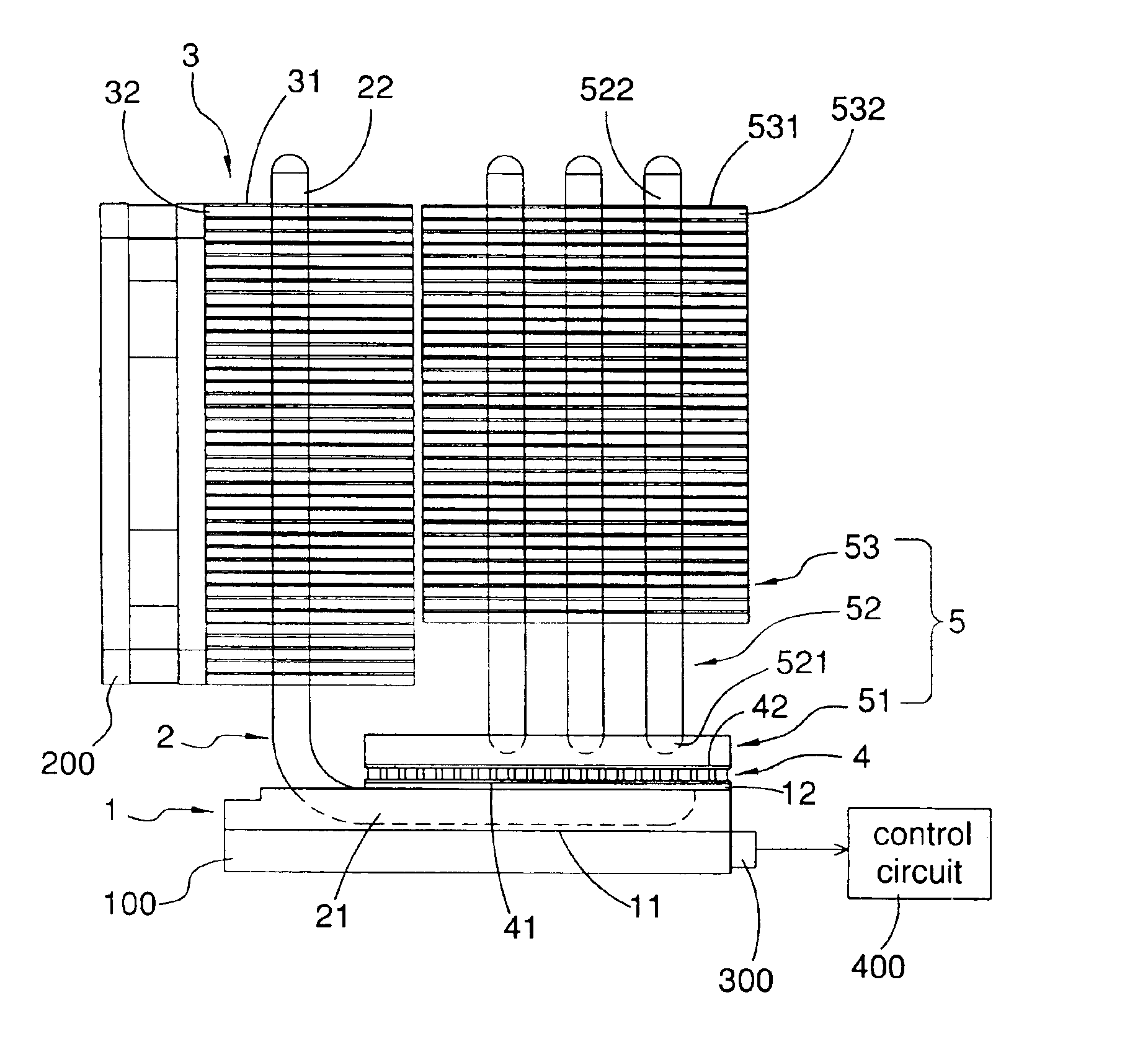
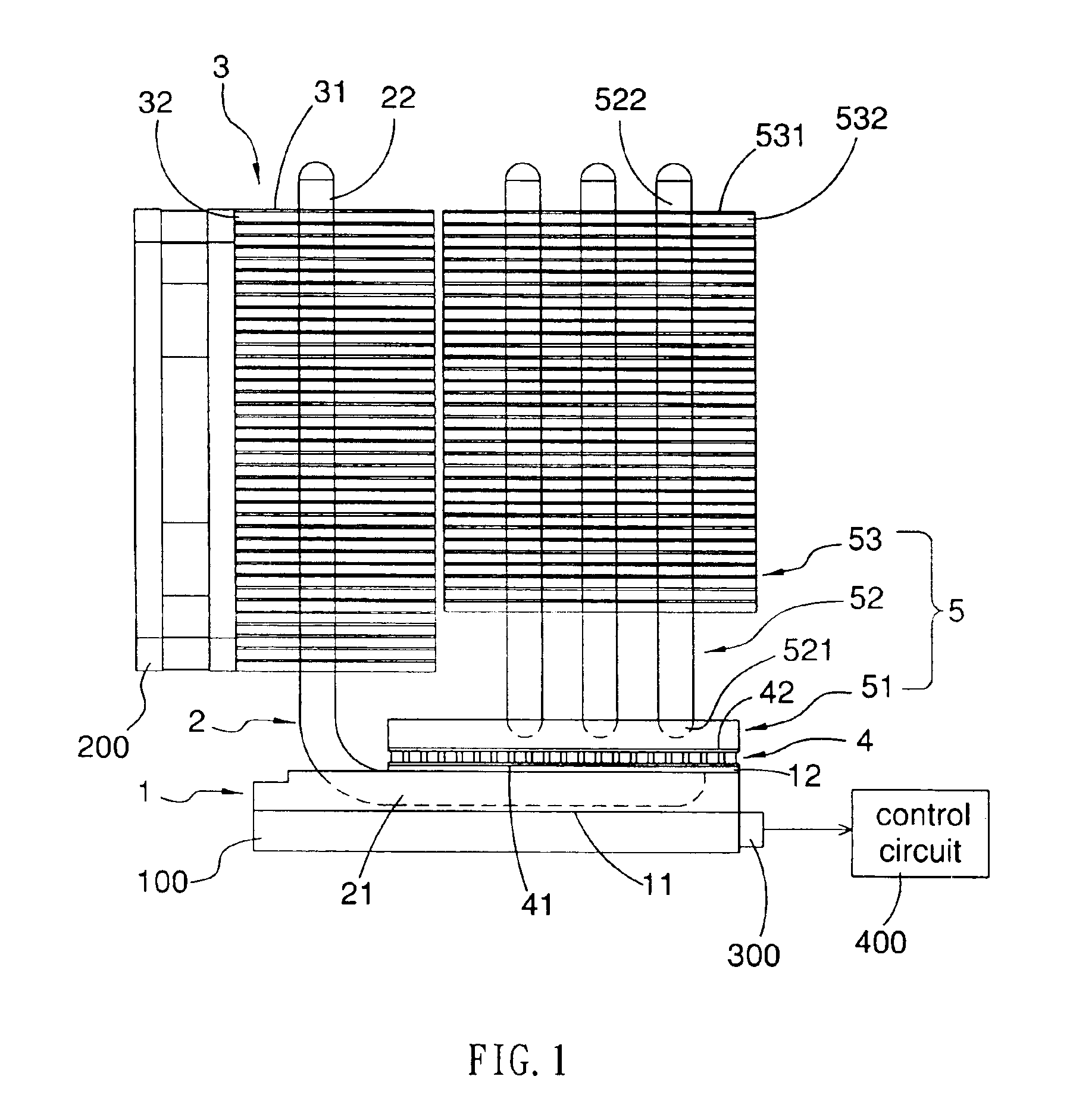
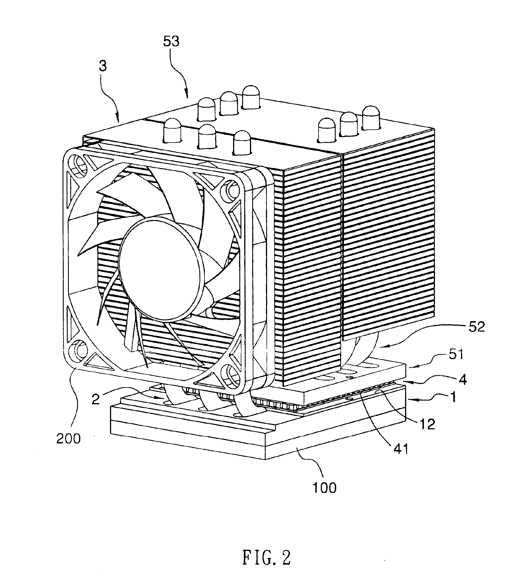
[0024]With reference to FIG. 1 to FIG. 3, the present invention is for cooling a CPU 100. The thermoelectric cooling apparatus contains a front heat absorbing block 1, three front heat pipes 2 (front heat conductive device), a front radiator 3, a thermoelectric cooler 4, and a back radiating module 5. The front heat absorbing block 1 has a first surface 11 and a second surface 12. The first surface 11 is the opposite side of the second surface 12 and the first surface 11 contacts the CPU 100. Each of the front heat pipes 2 has a first portion 21 and a second portion 22. The first portion 21 is connected with the front heat absorbing block 1. The second portion 22 extends from an end of the first portion 21 to a remote end away from the front heat absorbing block 1. The three front heat pipes 2 are parallel to each other. The front radiator 3 is connected with the second portions 22 of the three front heat pipes 2. The thermoelectric cooler 4 has a cold side 41 and a hot side 42. The...

second embodiment

[0030]With reference to FIGS. 5-8, the present invention for cooling the CPU 100 mainly contains: a front heat absorbing block 1a, three front heat pipes 2a (front heat conductive device), a front radiator 3a, two thermoelectric coolers 4a, and two back radiating modules 5a. The front heat absorbing block 1a has a bottom surface 11a and two side surfaces 12a, 13a. The bottom surface 11a contacts the CPU 100. Each of the front heat pipes 2a has a first portion 21a and a second portion 22a. The first portion 21a is connected with and embedded in the front heat absorbing block 1a. The second portion 22a extends from an end of the first portion 21a to a remote end away from the front heat absorbing block 1a and crooked into the front radiator 3a. One front heat pipe 2a has the second portion 22a extends from one direction and the other two front heat pipe 2a has the second portions 22a extends from the opposite direction. Each of the two thermoelectric coolers 4a has a cold side 41a and...

third embodiment

[0035]With reference to FIG. 9, the third embodiment contains a front heat absorbing block 1b, a water-cooling loop 2b, a front radiator 3b, a thermoelectric cooler 4b, a back radiating module (a back heat absorbing block 51b) and a pump 500. The front heat absorbing block 1b has a first surface 11b and a second surface 12b. The first surface 11b is the opposite side of the second surface 12b and contacts the CPU 100. The thermoelectric cooler 4b has a cold side 41b and a hot side 42b. The cold side 41b is the opposite side of the hot side 42b. The cold side 41b contacts the second surface 12b of the front heat absorbing block 1b for transmitting heat collected from the front heat absorbing block 1b from the cold side 41b to the hot side 42b. The back heat absorbing block 51b contacts the hot side 42b of the thermoelectric cooler 4b. In addition, the water-cooling loop 2b is arranged for systematically linking up the front heat absorbing block 1b, the back heat absorbing block 51b, ...


PUM


Abstract

The present invention provides a thermoelectric cooling apparatus for cooling an electronic device such as a CPU, or a computer chip. The apparatus cools the electronic device by two stages. In the first stage, a heat absorbing block collects the heat produced by the electronic device and the apparatus pre-cools the electronic device by dissipating a portion of the collected heat in a distant location through a front heat conductive device and a front radiator. Thereby the heat of the electronic device is reduced to a degree that a TEC can efficiently handle. In the second stage, a TEC of the apparatus dissipate the residual of the heat produced by the electronic device through at least a back heat pipe and a back radiator.

Description

TECHNICAL FIELD[0001]This invention relates generally to a thermoelectric cooling apparatus, in particular, a two stage radiation thermoelectric cooling apparatus for cooling an electronic device.BACKGROUND OF THE INVENTION[0002]Central Processing Units (CPUs) of computers generate large quantities of heat during operation, especially as the speed of operation increases. However, this heat, if confined in the computer housing, can affect the operation and reliability of many heat sensitive elements forming parts of the computer, including the CPU itself, motherboard components, memory, CD ROM, CDRW, DVD, hard drive, Disk on Chip, Magnetic media, floppy drives, electronic cards, etc especially in personal computers, industrial computers, servers, workstations, mainframes, other computers and telecommunication devices.[0003]A conventional cooler for cooling an electronic device such as CPU mainly contains a heat sink and a fan. The heat sink is made of copper or aluminum. The heat sin...

Claims


Application Information

Patent Timeline
IPC IPC(8): F25B25/00F25B21/02H01L23/467H01L23/38H01L23/34H01L35/28H01L35/30H01L23/427
CPCF25B21/02F25B25/005H01L23/38H01L23/467H01L35/30F25B2321/0212F25B2321/0251F25B2321/0252H01L2224/16H01L23/427F25D2700/16F28D15/0275H10N10/13
Inventor TSENG, HSIANG-CHIEHLIU, YI-SONGCHOU, CHIA-MINYEH, CHIA-FENG
Owner GIGA BYTE TECH CO LTD
Why Eureka
Try Eureka