Robotic device for locomotor training

Inactive Publication Date: 2005-04-19
RGT UNIV OF CALIFORNIA
View PDF18 Cites 67 Cited by
  • Summary
  • Abstract
  • Description
  • Claims
  • Application Information

AI Technical Summary

Benefits of technology

[0019]It is an object of the present invention to provide a robotic locomotion training system that is useful as a small-scale, well controlled test bed for evaluating the eng

Problems solved by technology

Paralysis of the legs is a common consequence of spinal cord injury, resulting in loss of walking ability.
It is assumed that partially unloading the limbs is the best approach for training primarily because coordinated stepping movements are difficult to elicit with full weight bearing using current weight support techniques.
As a consequence, current techniques cannot provide greater than normal loading on the limbs or be

Method used


Image

  • Robotic device for locomotor training
  • Robotic device for locomotor training
  • Robotic device for locomotor training

Examples


example 1

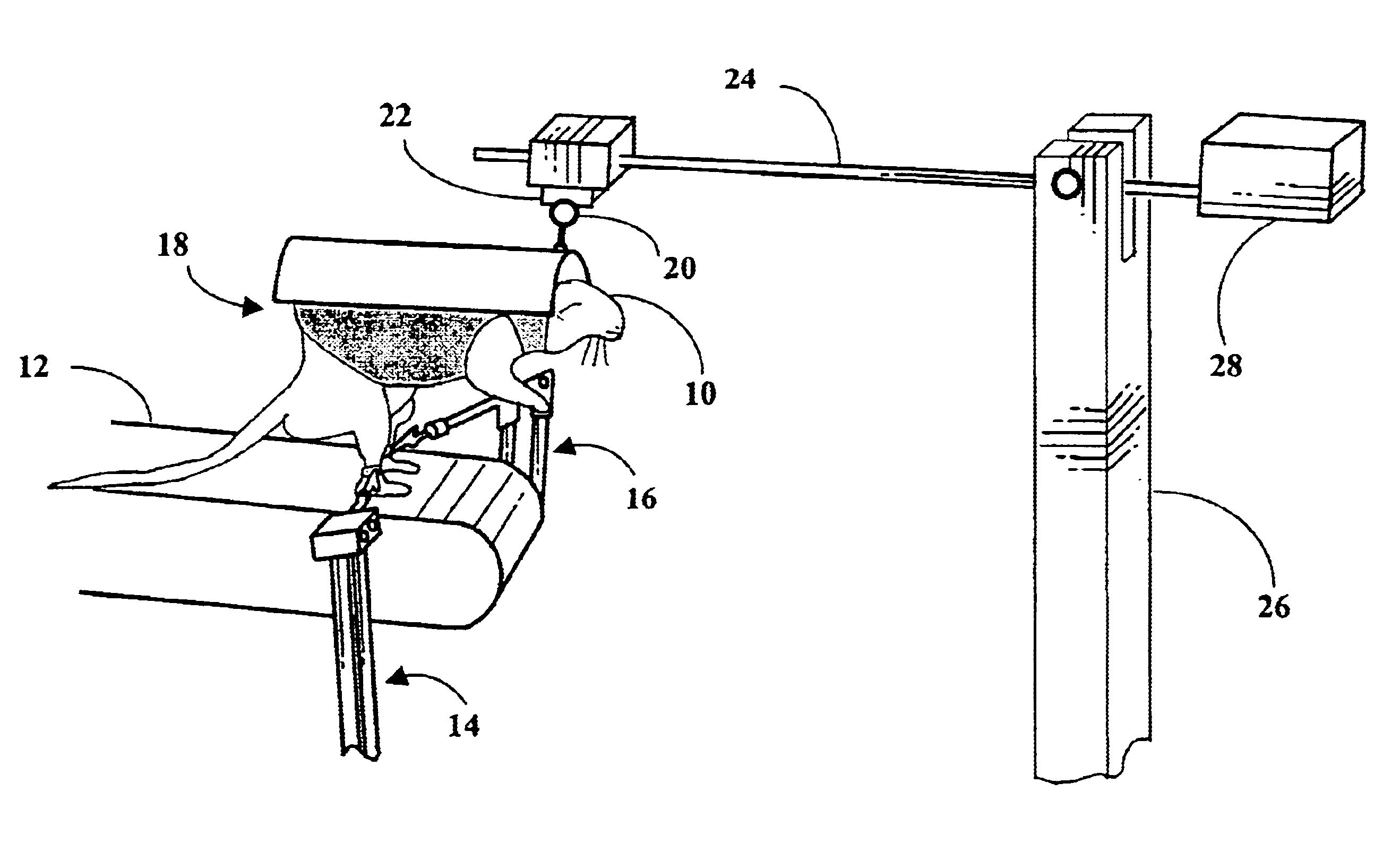
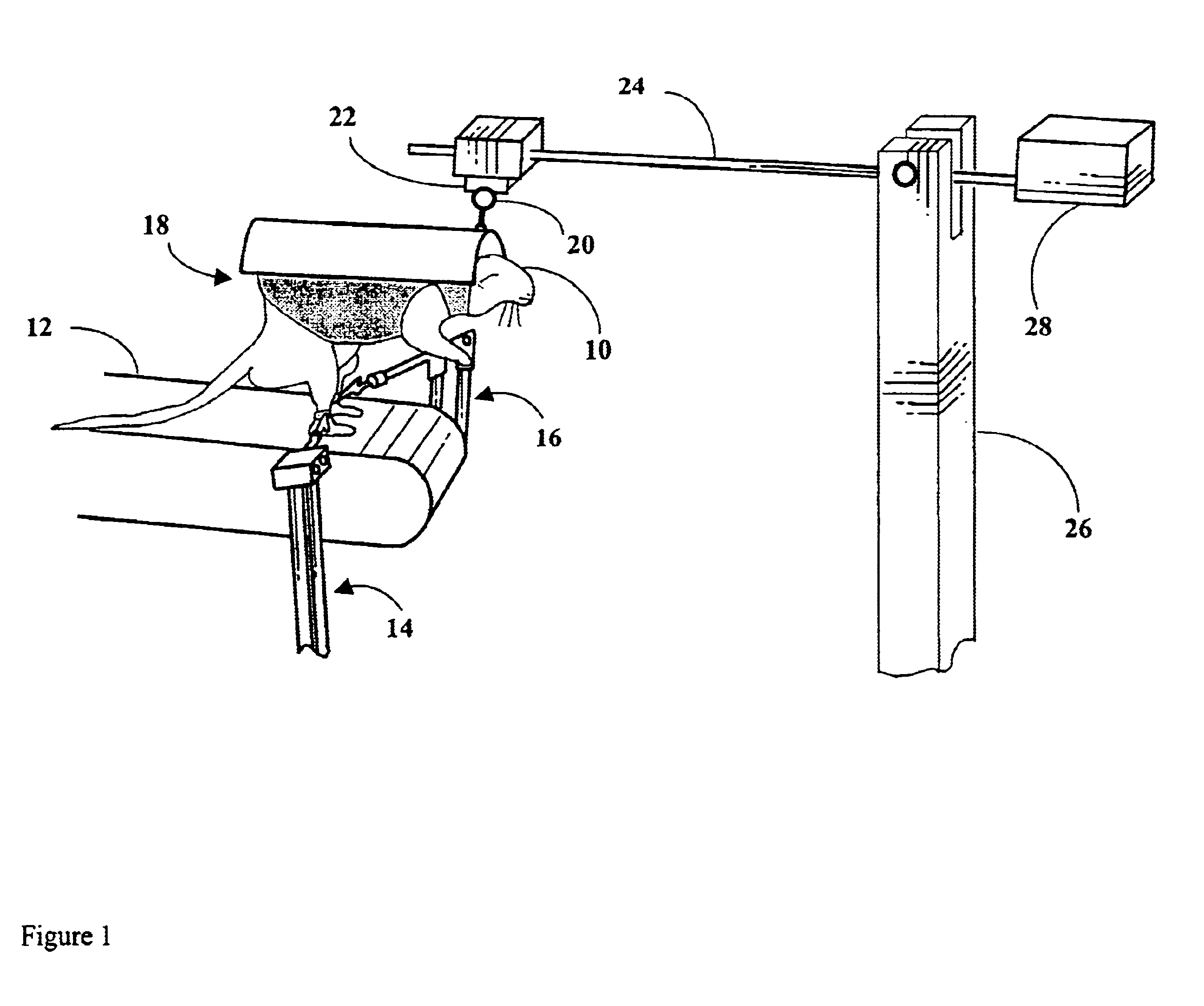
[0066]This example shows that training with the robotic locomotion system improves stepping of spinal transected rats. Rats received complete spinal cord transections five days after birth and began training (two hours of training per week for eight weeks) shortly after weaning. The amount of weight support during training was adjusted to allow a load level on the hindlimbs that was equivalent to half of normal levels. During training over a moving surface provided by a conveyor belt, a Phantom 1.0 robotic arm was attached to each hindlimb shank by a neoprene cuff to record and quantify hindlimb trajectories. In this example, the robotic arms did riot apply assistive force during stepping. Instead, the arms moved passively with the hindlimbs.

[0067]A graph of stepping ability of trained and non-trained spinal transected rats is shown in FIG. 11. Each point on the graph represents the number of rats that successfully stepped on a certain week after training started. Successful steppin...

example 2

[0068]This example shows a way to robotically measure limb movement characteristics of a spinal transected rat during locomotion training. Transections were performed five days after birth, as a more robust recovery of stepping occurs when transections are performed shortly after birth. The transected rat pup was returned to its mother until the pup reached 21 days of age. The rat was then trained two to three times a week for 5-10 minutes per day to perform bipedal, hindlimb stepping on a physical treadmill. Training consisted of manually holding the rats above a treadmill to allow a sufficient amount of loading on the hindlimbs. In this example, the rat was two months old, and could perform alternating, weight-bearing hindlimb stepping on a physical treadmill. However, the rat sometimes failed to initiate swing or dragged its toes during swing. All experiments followed the guidelines of the Animal Use Committee of the University of California, Los Angeles.

[0069]Each hindlimb of th...

example 3

[0073]This example shows that step cycle characteristics are not significantly altered by attachment of robotic arms to rat hindlimbs. Each hindlimb shank was attached to a Phantom 1.0 robotic arm using a neoprene cuff. Rats were suspended from a manually adjustable harness over a conveyor belt moving at a speed of about 11 cm / s. Body weight load was about 75%. Conventional kinematic film analysis was used to compare hip, knee and ankle joint angle displacements at various key points in the step cycle, such as toe off and paw contact, while rats stepped with and without the robotic arms attached. As shown in FIG. 12, hip and knee joint angles with attached robotic arms (white bars) were similar to the corresponding joint angles without attached robotic arms (black bars). For the ankle joint, only slightly greater flexion was apparent as a result of robotic arm attachment.


PUM


Abstract

A robotic system and method for locomotion assessment and training of a mammal, exemplified by a rodent. A neurologically impaired animal is suspended over a moving surface in a harness, and the animal's hindlimbs are connected to robotic arms that apply force to the hindlimbs or measure limb movement characteristics. The moving surface can be a physical or virtual surface. A single robotic mechanism comprising two robotic arms can simultaneously apply force, measure limb movement, and provide a virtual surface. Manual or automatic adjustment of load support allows the mammal to step at varying body weight loads.

Description

CROSS-REFERENCE TO RELATED APPLICATIONS[0001]This application is based on provisional application No. 60 / 282,208, filed on Apr. 5, 2001.STATEMENT REGARDING FEDERALLY SPONSORED RESEARCH OR DEVELOPMENT[0002]This invention was made with Government Support under Grant No. NS16333, awarded by the National Institutes of Health. The Government has certain rights in this invention.BACKGROUND[0003]1. Field of Invention[0004]The present invention relates generally to a robotic locomotor training device.[0005]2. Related Art[0006]In the U.S. alone, over 10,000 people experience a traumatic spinal cord injury each year, and over 200,000 people with spinal cord injury are alive (20). Paralysis of the legs is a common consequence of spinal cord injury, resulting in loss of walking ability. Recently, a new approach to rehabilitation called “body weight supported locomotion training” has shown promise (12, 14, 20, 34, 35, 37, 41, 42, 53, 54, 55, 56). The technique involves suspending a spinal cord i...

Claims


Application Information

Patent Timeline
IPC IPC(8): A01K15/02A01K15/00A61H3/00A63B22/00A63B22/02
CPCA01K15/027A61H1/0262A61B5/112A61B5/1126A61H3/008A61H2203/03A63B22/02A61H2201/5061A61B2503/40A61H2201/1215A61H2201/1642A61H2201/1659A61H2201/1676A61B5/407
Inventor REINKENSMEYER, DAVID J.TIMOSZYK, WOJCIECHLONDON, NIKOLASDE LEON, RAY D.EDGERTON, V. REGGIE
Owner RGT UNIV OF CALIFORNIA
Why Eureka
Try Eureka