Heat treating plant, installation method for porous regenerative element, production method for heat treated substance, selection method for porous regenerative element, and spent porous regenerative element component member

a technology of porous regenerative elements and heat treatment plants, which is applied in indirect heat exchangers, lighting and heating apparatuses, furnaces, etc., can solve the problems of periodic or non-period replacement of porous regenerators, severe chemical reactions of porous heat accumulating bodies, and deterioration of properties and quality of porous regenerators, so as to increase the operating period of time

Inactive Publication Date: 2005-04-19
NIPPON KOKAN KK +2
View PDF11 Cites 26 Cited by
  • Summary
  • Abstract
  • Description
  • Claims
  • Application Information

AI Technical Summary

Benefits of technology

[0048]A sixteenth aspect of the invention provides a selecting method of a porous regenerator to be built in a direct-fired burner or a heat exchanger provided in a regenerative combustor, comprising the steps of measuring a decrease in the substantial average surface pore diameter of the porous regenerator occurring along with a increase in

Problems solved by technology

Depending upon the kind of heat treatment carried out in the heating chamber, the porous heat accumulating body may be exposed to severe chemical reactions.
Since it is used under severe conditions, it is inevitable to periodically or non-periodically replace the porous regenerator.
These by-products or residual off-purpose substances occur or deposit in the pores of the porous regenerator, causing choking or clogging of pores (hereinafter referred to as “choking” or the porous regenerator for convenience sake), resulting in deterioration of properties and quality of the porous regenerator with the lapse of time in service as compared with an originally expected level.
As a result, a sudden increase in gas pressure is caused in the heating chamber, and combustion efficiency of a direct-fired burner, heat exchange efficiency of a regenerative heat exchanger, or performance as a whole also decreases, thus impairing efficient operation of the heat treatment equipment.
Unless choking of the porous regenerator is effectively prevented or inhibited, extending the service life is limited, so that the period for maintenance work such as inspection, maintenance, replacement, cleaning and the like of the porous regenerator cannot be increased to be over a certain level.
This means that the frequency of these maintenance operations cannot be reduced to be under a certain level.
However, this causes an increase in the cost for maintenance works (including personnel cost and overhead).
For example, a porous regenerator is unavailable without compensation.
The increase in the replacement frequency of the porous regenerator is directly associated with the increase in maintenance and management cost of the heat treatment equipment.
Even when maintenance is required only for some porous regenerators, it is sometimes necessary to discontinue operation of the heat treatment equipment.
As a result, this leads to an increase in frequency of maintenance operations, causes troubles in operation of the heating equipment, and poses problems in operating cost.
However, choking of the porous regenerator becomes more serious with the lapse of time

Method used


Image

  • Heat treating plant, installation method for porous regenerative element, production method for heat treated substance, selection method for porous regenerative element, and spent porous regenerative element component member
  • Heat treating plant, installation method for porous regenerative element, production method for heat treated substance, selection method for porous regenerative element, and spent porous regenerative element component member
  • Heat treating plant, installation method for porous regenerative element, production method for heat treated substance, selection method for porous regenerative element, and spent porous regenerative element component member

Examples


Embodiment Construction

[0078]First, the terms in the present invention will be defined.

1. “Porous Regenerator”:

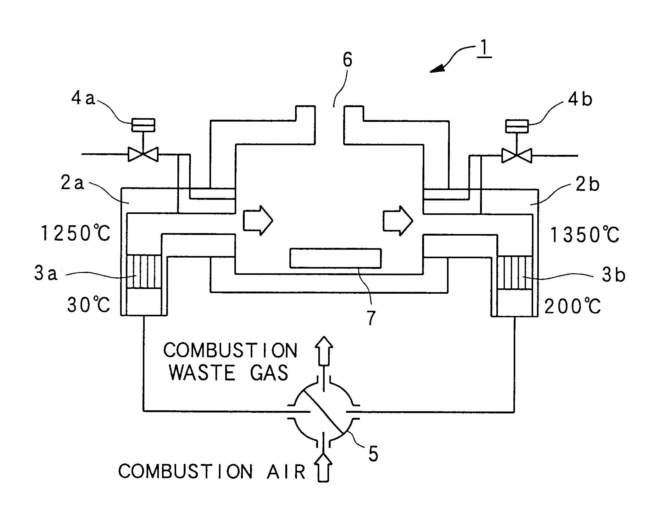
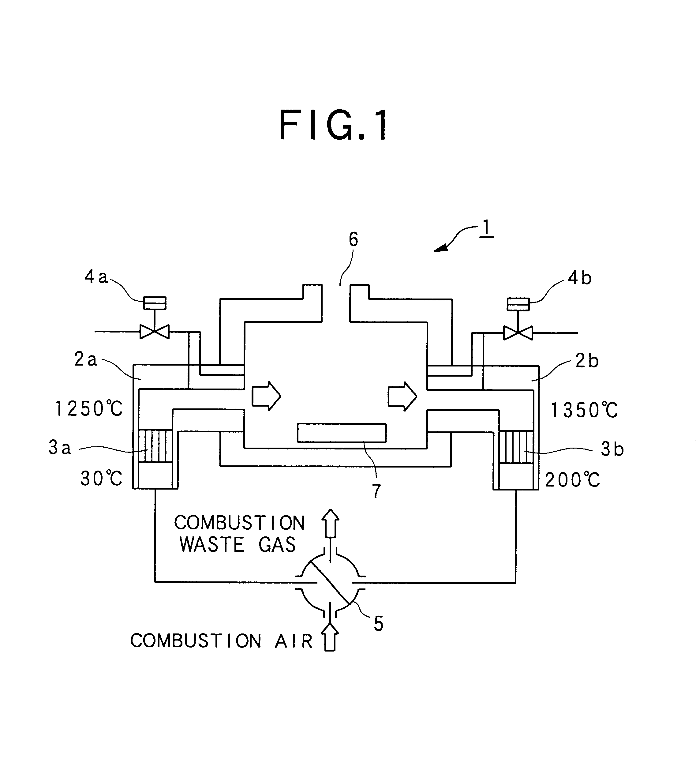
[0079]The term “porous regenerator” means a structure which comprises one or more members, has a regenerative function as a whole, and is provided with a plurality of connection paths of pores or gaps deemed as pores (hereinafter referred to as “false pores”). The individual members may have any of various shapes including a block shape, a ball shape, a flake shape and a nugget shape (for example, Japanese Unexamined Utility Model Registration No. 7-2739 and Japanese Unexamined Patent Application Publication No. 8-94066).

[0080]From the point view of “porous”, “pores” or “false pores”, a honey-comb-shaped member itself has many pores, and can serve as a porous regenerator in the present invention. However, when using a collection of a plurality of honey-comb members as a whole as a regenerator (for example, Japanese Unexamined Patent Application Publications Nos. 7-280239, 8-247671, and 7-39761, a...


PUM


Abstract

A heat treatment equipment having a heating chamber having a plurality of regenerative combustors provided with direct-fired burner having a built-in porous regenerator, for applying a heat treatment to an object in the heating chamber, wherein the substantial average surface pore diameter is not uniform for porous regenerators in a plurality of direct-fired burners or a plurality of regenerative combustors. By making contrivances in the shape of porous regenerators of the direct-fired burners or the regenerative heat exchangers arranged in an area where substances causing choking tend to easily adhere to make it difficult for such substances to adhere or prevent choking phenomenon from becoming apparent.

Description

BACKGROUND OF THE INVENTION[0001]1. Field of the Invention[0002]The present invention relates to a heat treatment equipment provided with a heating chamber having a plurality of regenerative combustors each provided with a direct-fired burner having a porous heat accumulating body built therein and applying a heat treatment to an object in the heating chamber; an installing method of a porous heat accumulating body when applying a heat treatment to the object in the heating chamber having a plurality of such regenerative combustors; and a manufacturing method of a heat-treated object using such a heat treatment equipment; a heat treatment equipment provided with a space in which a plurality of heat exchangers each having a built-in porous heat accumulating body are attached; an installing method of a porous heat accumulating body in such a heat treatment equipment; and a manufacturing method of a heat-treated object, using such a heat treatment equipment. More particularly, the inve...

Claims


Application Information

Patent Timeline
IPC IPC(8): F23L15/00F23L15/02F28D20/00
CPCF23L15/02F28D20/0056F23L2900/15021Y02E60/142F23L2900/15022Y02E20/34Y02E60/14F27B19/00
Inventor SUZUKAWA, YUTAKAMORI, ISAONAGOSHI, MASAYASUTADA, TAKESHISUDO, JUNKASAI, YOSHIYUKIUMEHARA, KAZUHIKO
Owner NIPPON KOKAN KK
Why Eureka
Try Eureka