Optical module

Inactive Publication Date: 2005-04-19
HAMAMATSU PHOTONICS KK
View PDF6 Cites 13 Cited by
  • Summary
  • Abstract
  • Description
  • Claims
  • Application Information

AI Technical Summary

Benefits of technology

[0008]In the optical module according to the present invention, where the optoelectronic component is a light emitting device such as a laser diode, light emitted from the light emitting device is collimated into parallel light beam (including light of nearly parallel bead; the same will also apply to the description hereinafter) by the first lens and the parallel light beam travels through the second lens to be focused thereby on the core of the optical fiber. Since the light passing between the first lens and the second lens is the parallel light beam as described above, tolerance is enlarged for axial misalignment between the optical axes of the first lens and the second lens. This enables the light from the light emitting device to be focused on the core of the optical fiber even if there occurs axial misalignment between the optical axes of the optical fiber and the light emitting device due to a factor resulting from the fitting between the ferrule and the sleeve, for example. In the case where the optoelectronic component is a photodetector such as a photodiode, light emerging from the optical fiber is collimated into parallel light beam by the second lens and the parallel light beam travels through the first lens to be focused thereby on the photodetector. Accordingly, just as in t

Problems solved by technology

However, the optical module as described above requires a device dedicated to the alignment and also takes a

Method used


Image

  • Optical module
  • Optical module
  • Optical module

Examples


first embodiment

[First Embodiment]

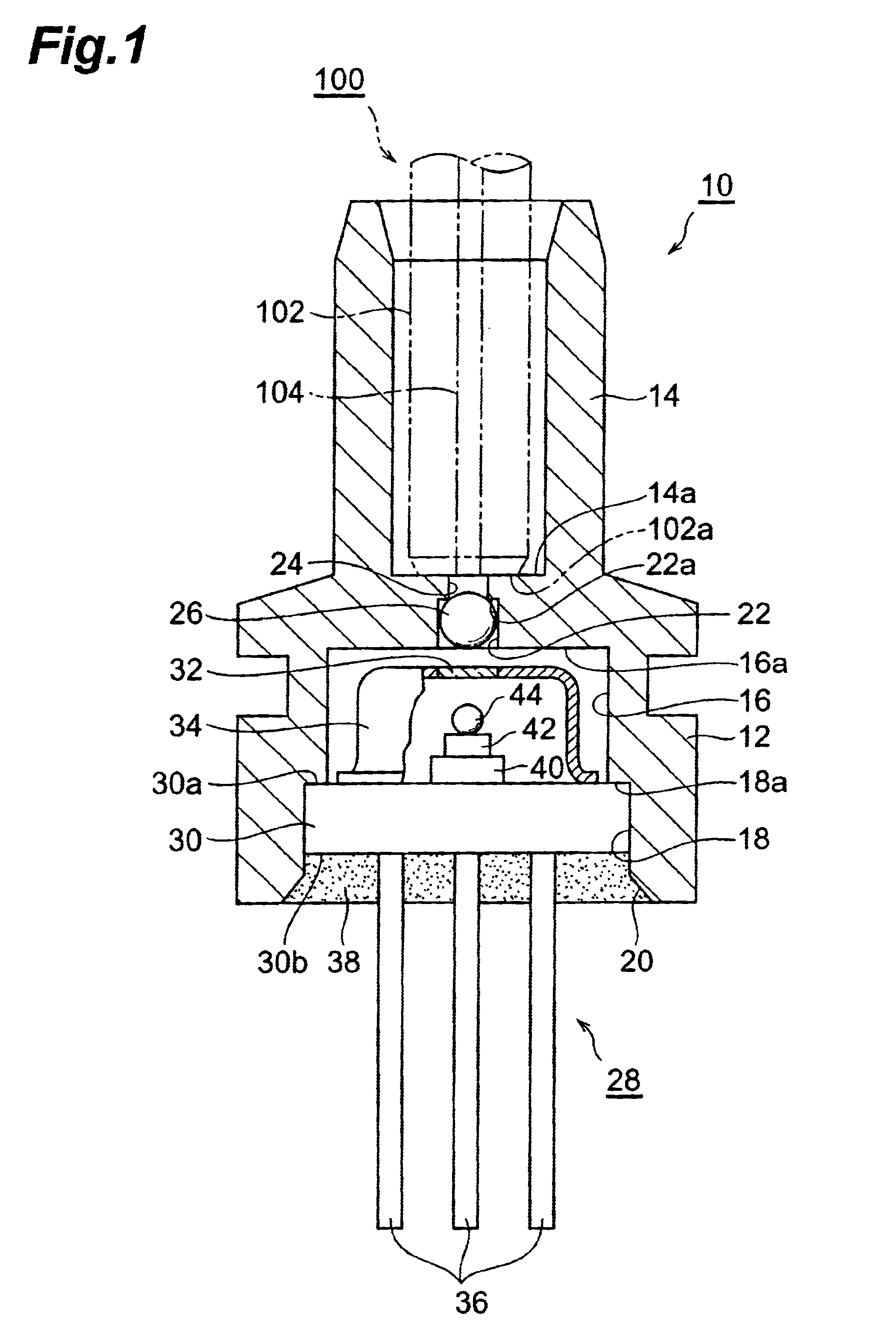
[0015]As shown in FIG. 1, optical module 10 has housing 12 integrally molded of epoxy resin. Sleeve 14 with ferrule 102 of optical fiber 100 being fitted therein is formed at one end of housing 12, and bottom surface 14a inside sleeve 14 functions as a ferrule stopper in contact with ferrule end face 102a. The optical fiber 100 is a multi-mode optical fiber for optical communications and has core 104 with the core diameter Φ of 50 μm.

[0016]On the other hand, recess 16 of a circular cross section is formed at the other end of housing 12. Larger-diameter recess 18 of a circular cross section having the diameter greater than that of recess 16 is formed on the aperture side of the recess 16, and inner chamfer 20 is made at an aperture portion of this larger-diameter recess 18. Smaller-diameter recess 22 of a circular cross section having the diameter smaller than that of the recess 16 is formed in bottom surface 16a of recess 16 and a light passing hole 24 is formed be...

second embodiment

[Second Embodiment]

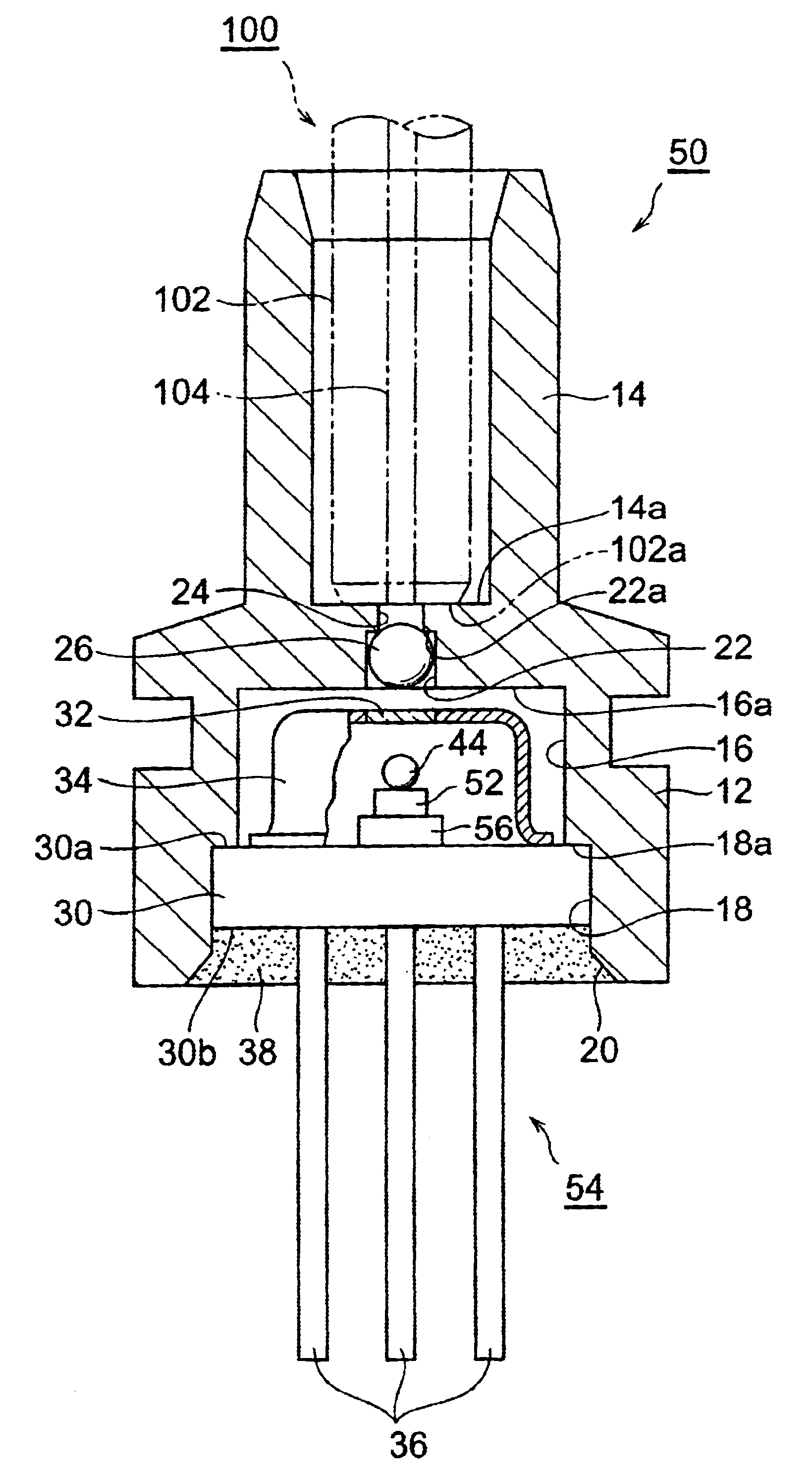
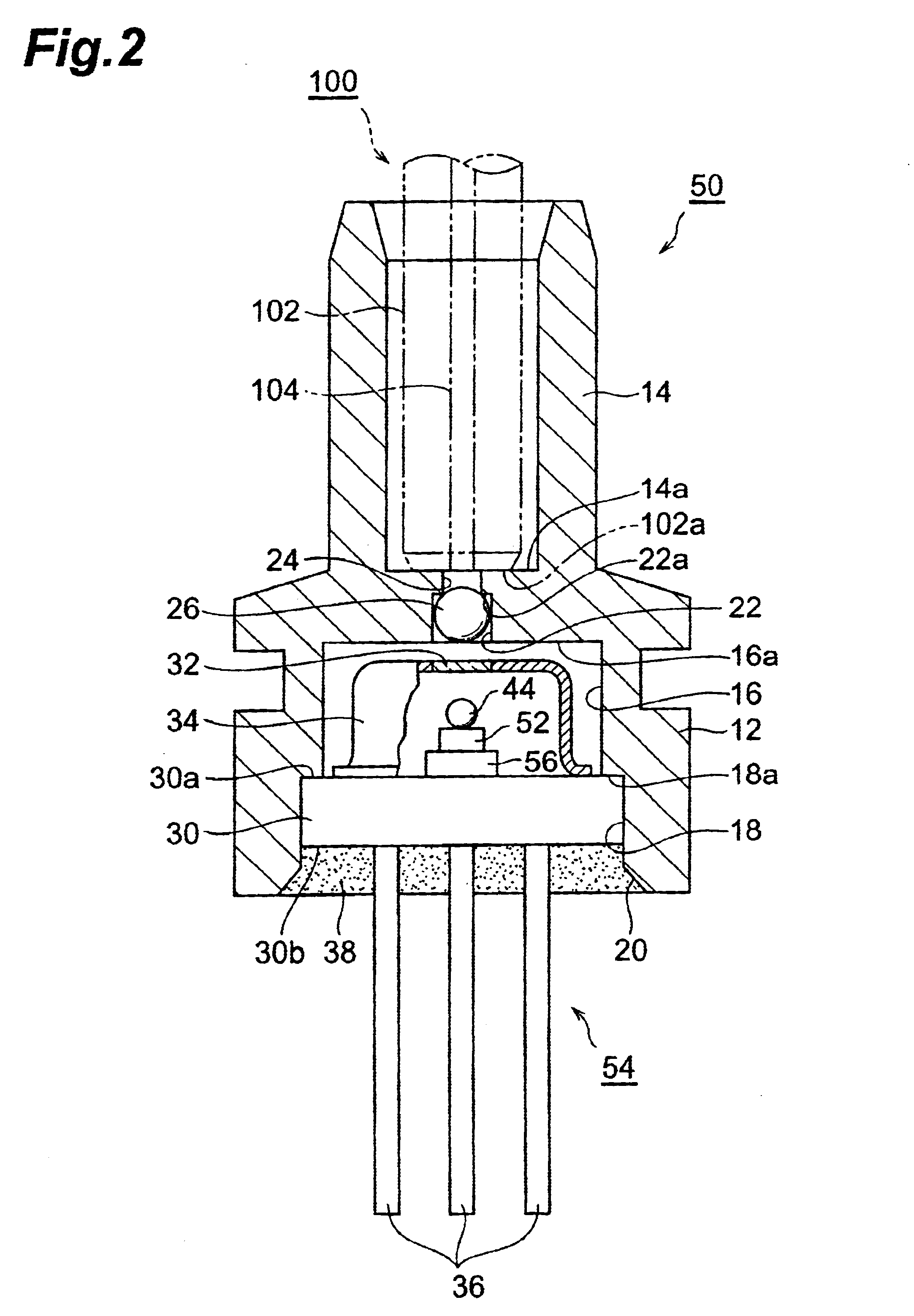
[0029]Another embodiment of the optical module according to the present invention will be described below with reference to the drawing. In the optical module according to the present invention, the optoelectronic device applicable thereto may be one having a photodetector such as a photodiode, or one having an optical waveguide element. The optical module 50 shown in FIG. 2 is one to which optoelectronic device 54 having photodiode 52 is applied. In the description hereinafter, identical or similar portions to those in the above embodiment will be denoted by the same reference symbols, without redundant description thereof.

[0030]In optical module 50, as shown in FIG. 2, optoelectronic device 54 with photodiode (photodetector) 52 is housed in housing 12. In the hermetic space inside cap 34 of optoelectronic device 54, sub-mount 56 is die-bonded on one end face 30a of stem 30, and photodiode 52 is die-bonded on this sub-mount 56. Furthermore, ball lens 44 having th...


PUM


Abstract

In optical module 10, light emitted from laser diode (hereinafter referred to as “LD”) 42 is collimated into parallel light beam by ball lens 44 and then travels through ball lens 26 to be focused on core 104 of optical fiber 100. Since the light passing between ball lenses 44 and 26 is the parallel light beam as described above, allowance is enlarged for axial misalignment between the optical axes of ball lens 44 and ball lens 26. This enables the light from LD 42 to be focused on core 102 of optical fiber 100 even if there occurs axial misalignment between the optical axes of optical fiber 100 and LD 42 due to a factor resulting from fitting of ferrule 102 into sleeve 14 or the like. Accordingly, there is no need for alignment in a work of mounting optoelectronic device 28, i.e., LD 42 in housing 12.

Description

BACKGROUND OF THE INVENTION[0001]1. Field of the Invention[0002]The present invention relates to an optical module for optically coupling an optoelectronic component to an optical fiber, which is used mainly in optical communications.[0003]2. Related Background Art[0004]A conventionally known optical module for optically coupling an optoelectronic component to an optical fiber is, for example, the one described in Japanese Patent Application Laid-open No. 08-234058. The optical module described in this Application is of such structure that in a housing a sleeve with a ferrule of an optical fiber fitted therein is disposed through a SELFOC lens or the like on the optical axis of an optoelectronic component. In the optical module of this type, the following alignment is achieved in a work of fixing the optoelectronic component to the housing with UV-curing adhesive or the like. Namely, in the case of the optoelectronic component being a light emitting device, the light emitting device...

Claims


Application Information

Patent Timeline
IPC IPC(8): G02B6/42H01L31/0232H01L33/58
CPCG02B6/4292G02B6/4204
Inventor HOSHINO, YASUJIWARASHINA, YOSHIHISAIYAMA, SHOGOTAKEYAMA, HAJIME
Owner HAMAMATSU PHOTONICS KK
Why Eureka
Try Eureka