Frame connection mechanism

a frame connection and mechanism technology, applied in the direction of rod connection, manufacturing tools, building scaffolds, etc., can solve the problems of rust and erioration of welded joints, difficulty in undoing of welded joints, and many structural problems, so as to reduce shipping costs, avoid damage to the structure in transit, and the effect of the same strength

Inactive Publication Date: 2005-04-19
SOSA SAUL SINEY
View PDF19 Cites 23 Cited by
  • Summary
  • Abstract
  • Description
  • Claims
  • Application Information

AI Technical Summary

Benefits of technology

[0017]The instant invention provides an assembly which can readily be substituted for welded tubing assemblies. The invention is especially useful in those environments where welding is very difficult to perform either due to the size of the structure or the presence of material which is either inflammable or subject to damage from the heat incident to welding, e.g. plastic. The assembly of the present invention is capable of producing joints which have the same strength if not greater strength than the tubing being utilized. Furthermore, in many instances, the newly produced joints may be stronger than welded joints in that the present invention does not weaken the finished structure or create the opportunity for deterioration from environmental hazards.
[0018]The nature of the instant invention permits the assembly to be shipped to the consumer in an unassembled condition thereby reducing shipping costs and avoiding damage to the structure in transit. Furthermore, given the specific configuration of the tubing elements, the user is able to adjust the size of the tubing elements on site to construct a structure of a desired dimension.

Problems solved by technology

The connections of one tubular element to another tubular element present several structural problems.
While welding can produce a strong joint between the elements, in these instances where the joint is exposed to the elements, welded joints are subject to rust and erioration.
Should the user wish to undo the connection between the elements, a welded joint can prove difficult to undo.
This removal of galvanized coating subjects the affected areas to the possibility of rusting.
Manufacturers of such gate frames have historically experienced difficulties in joining the various tubular elements together in a way which provides sufficient structural integrity while simultaneously ensuring adequate protection against rust and other forms of erioration from exposure to the elements.
While many of these prior constructions address some of the traditional concerns regarding gate constructions, these constructions have yet to meet all of the concerns raised by manufacturers, installers and consumers of such gate products.
This particular construction has several problems associated with it.
First, to obtain a weld securing the extension B to the upright A is difficult in practice.
Further, such a weld is subject to rust.
The removal of the galvanized coating creates the possibility of rust formation.
The use of welding to affix the extensions B to the upright render such adjustments difficult if not impossible one the weld has been made.
Secondly, the drilling of apertures C, H and G exposes portions of the otherwise galvanized extension and tubular member to rust, i.e. about the edges of the apertures.
Further, the use of the extension B requires the sheathing J, which is intended to cover the upright A, to be split longitudinally along its length in order to accommodate the extension B. Furthermore, an opening K must be defined within the sheath J to accommodate the extension B. It follows that not only is sheathing J difficult to manufacture, but furthermore, it is difficult to install.

Method used


Image

  • Frame connection mechanism
  • Frame connection mechanism
  • Frame connection mechanism

Examples


second embodiment

[0058]FIG. 8 illustrates an alternative first insert construction wherein the insert does not include an extension member 30. Instead, the endwall 37 defines the entry of a channel 52A which extends into the body of the insert 20. In this embodiment, the counterpart channel 58B extends completely through the body of the second insert 22. Furthermore, that portion of the channel 58 which extends beyond the countersink 58C is of a constant diameter over the length of the channel. The structure and operation of the second embodiment are essentially identical to the previously described embodiment except for the above described differences.

third embodiment

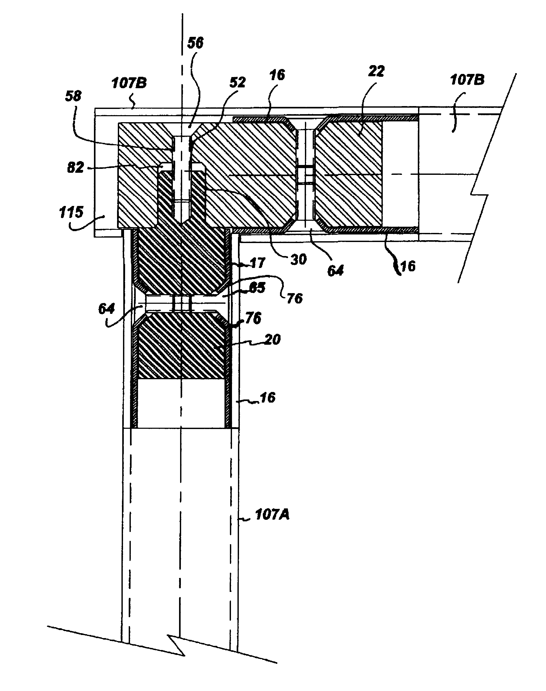
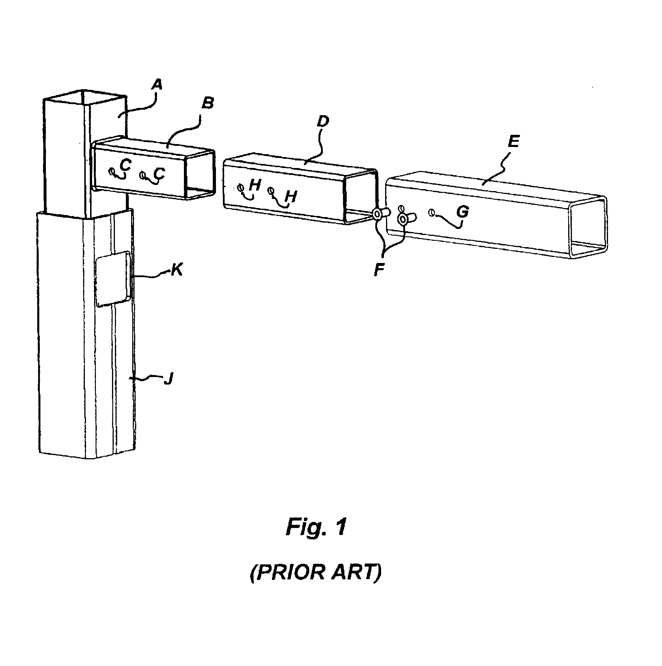
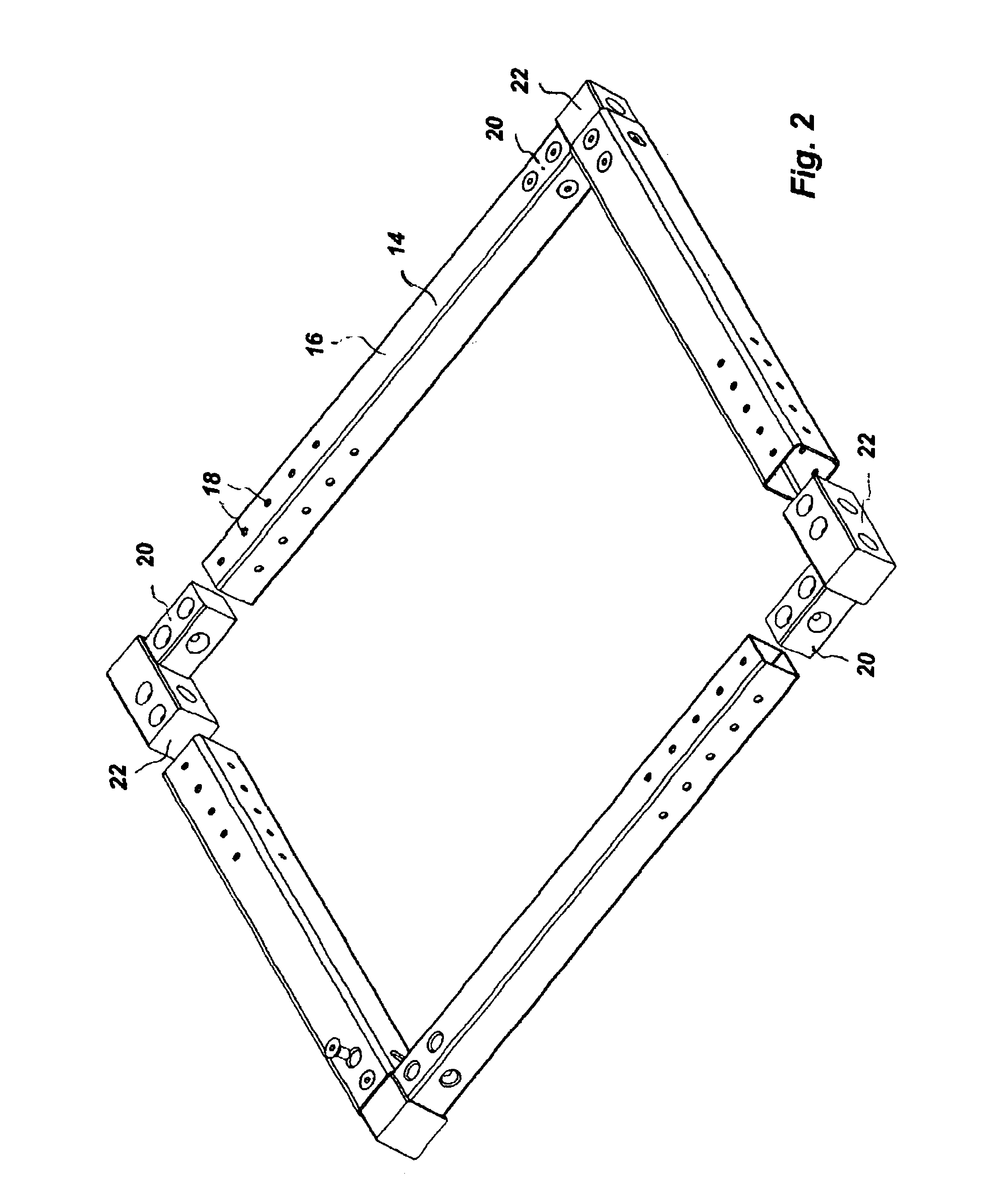
[0059]the invention is illustrated in FIGS. 9-12. This embodiment is adapted to form a “T” shaped union of three tubular elements, 16C, 16D, and 16E as illustrated in FIG. 12. Such a “T” union is oftentimes utilized to form a reinforcement structure for a conventional rectangular frame construction.

[0060]This embodiment includes a first insert 120 which is configured essentially identical to the first insert 20 described above. The second insert 122 is modified from the second insert 22 described above. As shown in FIG. 9 the second insert 122 is an elongate member having a quadrilaterally configured cross section and four planar sides. As shown in FIG. 9 the side 150 defines at least two channels 144A and 144B. Similar to the channels previously described, these two channels have a countersunk region which intersects the planar surface of the side of the insert. The channel extends symmetrically from the countersunk region into the body of the insert along a linear longitudinal axi...

first embodiment

[0062]As previously described with respect to the first embodiment, a connection member 164 is inserted into each of the apertures 118 which is aligned with a respective channel 140B or 140A. The connection member 164, which may be either a self tapping screw or alternatively a threaded bolt which is dimensioned to intercorporate with female threads formed on the interior sidewall of the respective channels 140A and 140B. Furthermore, the two tubular members 16C and 16D may be aligned to bring each of the channels 158A, 158B, 144A and 144B into registration with a respective aperture 118. A connection member 165 may then be inserted into each of the apertures 118 so aligned and thereafter into the counterpart channel 158A, 158B, 144A or 144B to form a threaded union of the tubular member with the second insert. Similarly, the third tubular member 16E may be slid into place about the first insert 120 to bring the channels 132 and 136 into registration with respective apertures 118. T...


PUM


Abstract

A frame connection structure for use in connecting tubular or open channel elements one to another includes two or more inserts configured for respective insertion within the elements to be interconnected. Each of the inserts defines one or more channels therein, each channel being configured to be aligned with a respective aperture defined within the tubular/open channel element in which it is to be retained. A connection member is positioned within each aperture and its aligned respective insert channel. A portion of the tubular/open channel member proximate the aperture is displaced into the channel of the insert member whereby the that portion of the tubular/open channel member is disposed intermediate the sidewall of the channel and the connection member. The two inserts are configured to be connectable one to another. Each insert is therefore securely associated with a respective tubular/open channel member and the inserts are connectable one to another to facilitate the construction of a frame assembly.

Description

BACKGROUND OF INVENTION[0001]1. Field[0002]This invention relates to structures for interconnecting two or more structural elements. More particularly, the invention is directed to structures for interconnecting tubular or open channel elements one to another.[0003]2. State of the Art[0004]Various structures are found by the interconnection of tubular elements in preselected arrangements. The connections of one tubular element to another tubular element present several structural problems. Traditionally, in the instance of tubular elements formed of metal, welding has been a common means of securing one element to another. While welding can produce a strong joint between the elements, in these instances where the joint is exposed to the elements, welded joints are subject to rust and erioration. Should the user wish to undo the connection between the elements, a welded joint can prove difficult to undo. Further, should these tubular elements be galvanized, then galvanized coating mu...

Claims


Application Information

Patent Timeline
Patent Type & Authority Patents(United States)
IPC IPC(8): E06B11/00E06B3/968E06B11/02E06B3/96E06B3/964F16B7/18E04B1/58
CPCE06B3/964E06B11/02F16B7/18E06B3/9687E04B1/5831E04B2001/5856Y10T403/7164Y10T403/7096F16B2200/67
Inventor SOSA, SAUL SINEY
Owner SOSA SAUL SINEY
Why Eureka
Try Eureka