
Measuring device using biosensor and biosenor used for it, and dedicated standard liquid

a biosensor and sensor technology, applied in the field of measuring devices, can solve problems such as difficulty for users with eyes and fingers, and achieve the effect of easy oxidation

Inactive Publication Date: 2005-04-19
PHC HLDG CORP
View PDF5 Cites 137 Cited by
  • Summary
  • Abstract
  • Description
  • Claims
  • Application Information

AI Technical Summary

Benefits of technology

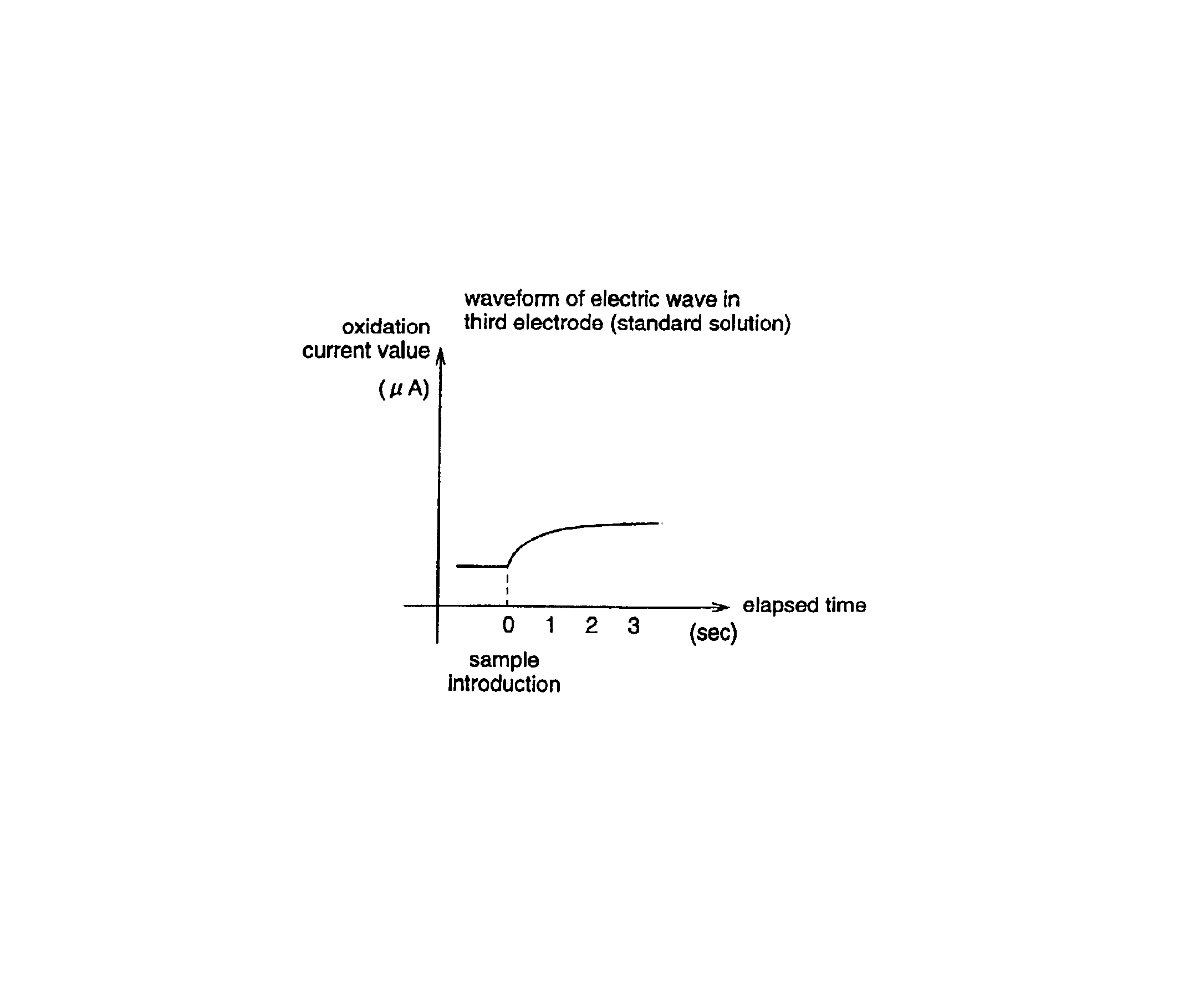
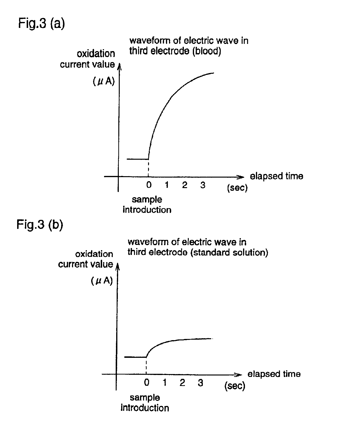
The present invention relates to a measuring apparatus using a biosensor for automatically judging the types of sample solution without artificial preoperation. The biosensor has a reaction layer that reacts with the substance to be measured in a sample solution, a working electrode, a counter electrode, and a third electrode. The types of sample solution can be automatically judged based on the oxidation current value obtained between the third electrode and the counter electrode or between the third electrode and the working electrode. The oxidation current value is measured without reference to a fixed threshold value, and the time variations of the oxidation current value are also used for automatic judgment. The biosensor can be easily used and has improved accuracy in identifying the types of sample solution.

Problems solved by technology

However, when a manual preoperation is necessary in the measuring apparatus, data is managed in a state where the standard solution measurement data is incorrectly recognized as the blood measurement data due to an artificial incorrect operation, a forgotten operation or the like.
More particularly, it is difficult for users having trouble with their eyes and fingers to perform the preoperation as described above, and therefore, a system which can automatically judge types of sample solution without operations has been desired.

Method used


Image

  • Measuring device using biosensor and biosenor used for it, and dedicated standard liquid
  • Measuring device using biosensor and biosenor used for it, and dedicated standard liquid
  • Measuring device using biosensor and biosenor used for it, and dedicated standard liquid

Examples


embodiment

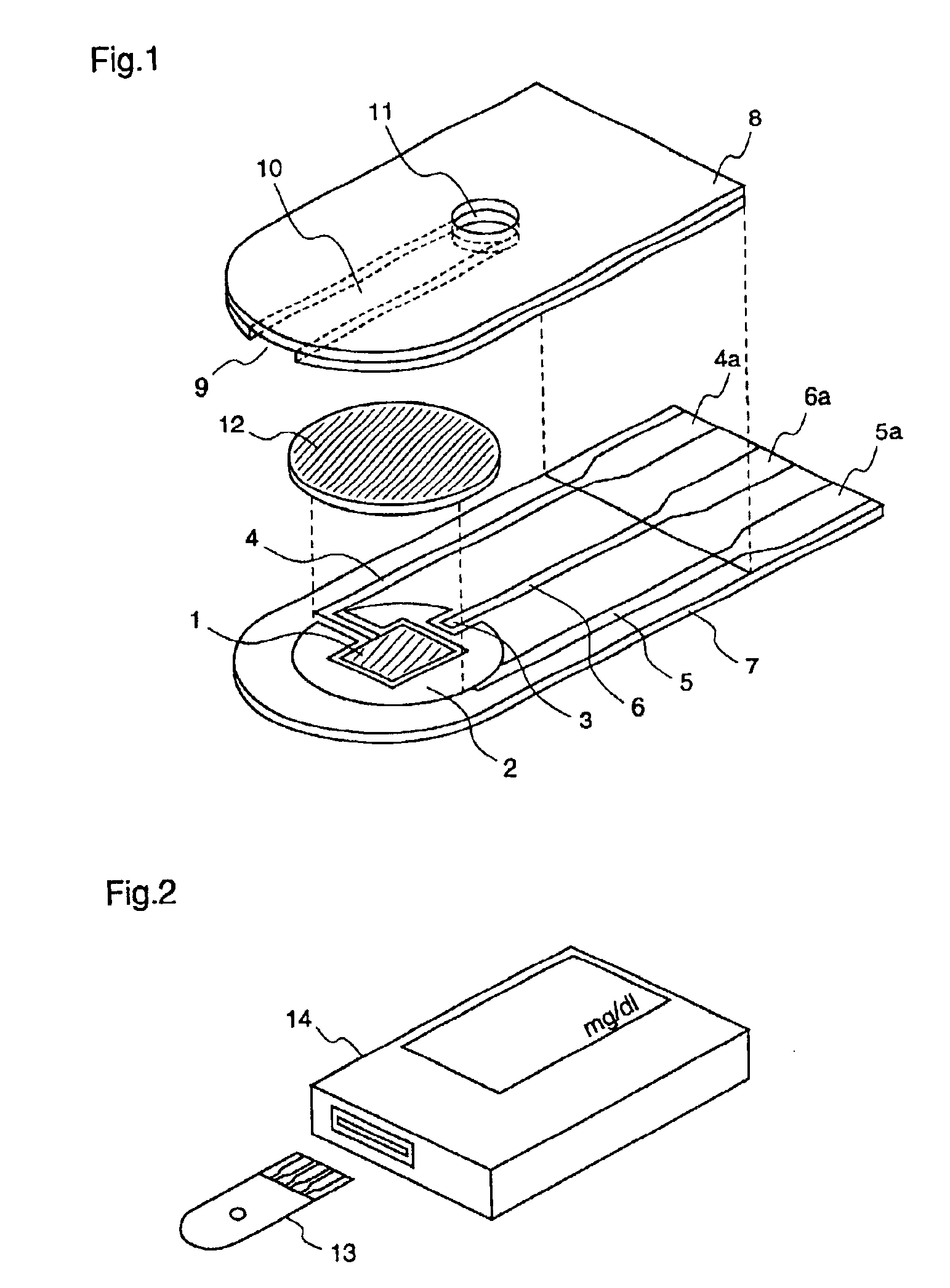
[0036]FIG. 1 is an exploded perspective view illustrating a structure of a glucose sensor according to an embodiment of the present invention. The same numerals are given to the similar components as those of the conventional sensor shown in FIG. 4.

[0037]In FIG. 1, a point that the sensor is different from the conventional sensor is that a silver lead 6 is further provided besides silver leads 4 and 5. On the tip of the silver lead 6, a third electrode 3 for judging types of sample solution is arranged on an air hole 11 side in the vicinity of the working electrode 1 and the counter electrode 2, and, on the other end, a connection terminal part 6a is further formed. Further, on the working electrode 1, the counter electrode 2, and the third electrode 3, the reaction layer 12 is formed so as to bridge and cover the working electrode 1, the counter electrode 2, and the third electrode 3. Further, as long as this third electrode 3 is arranged in a position where the third electrode 3 c...


PUM

PropertyMeasurementUnit
voltageaaaaaaaaaa
concentrationsaaaaaaaaaa

Abstract

A reaction layer 12 which reacts with a substance to be measured in a sample solution is provided on a working electrode 1, a counter electrode 2, and a third electrode 3 which are provided on an insulating substrate 7 so as to bridge the respective electrodes, the content of the substance to be measured is measured from a current value which reaction is obtained between the working electrode 1 and the counter electrode 2, and the types of sample solution is judged by a difference between oxidation current values or between oxidation current waveforms, which are obtained between the third electrode 3 and the counter electrode 2 or between the third electrode 3 and the working electrode 1, thereby automatically judging the types of sample solution.

Description

TECHNICAL FIELD[0001]The present invention relates to a measuring apparatus using an electrode type of biosensor, a biosensor used therefor, and an exclusive standard solution.BACKGROUND ART[0002]In recent years, for example, a small-sized simple glucose level measuring apparatus using an electrode type of biosensor has been used to diagnose a glucose level of diabetics and has been used in daily management. FIG. 4 is an exploded perspective view illustrating an example of a structure of a glucose sensor, and silver leads 4 and 5 are formed by a screen printing or the like on an insulating substrate 7 of PET (Polyethylene Terephthalate).[0003]A quadrangular working electrode 1 is formed by carbon on the tip of the silver lead 4, and a counter electrode 2 is formed so as to have a predetermined gap between the silver lead 5 and the working electrode 1 on the tip of the silver lead 5 and surround the working electrode 1. Terminal parts 4a and 5a connected to a measuring device at the ...

Claims


Application Information

Patent Timeline
Patent Type & Authority Patents(United States)
IPC IPC(8): G01N33/487G01N27/327
CPCG01N27/3273
Inventor TOKUNAGA, HIROYUKIMIYAZAKI, SHOJI
Owner PHC HLDG CORP
Learn More