Permanent magnet synchronous motor

Active Publication Date: 2005-04-19
MITSUBISHI ELECTRIC CORP
View PDF18 Cites 26 Cited by
  • Summary
  • Abstract
  • Description
  • Claims
  • Application Information

AI Technical Summary

Benefits of technology

[0010]The present invention aims to solve the above problems and an object of the present invention is to provide a permanent-magnet synchronous motor eliminating a deterioration in heavy load characteristics resulting from a slot opening being made narrow in a permanent-magnet synchronous motor previously proposed as an improvement by p

Problems solved by technology

Thus, with the magnetic poles generated by the stator coil and the magnetic poles of the permanent magnets opposing each other, one problem has been that portions of the magnetic fields generated by the stator coil enter the permanent magnets and act on the

Method used


Image

  • Permanent magnet synchronous motor
  • Permanent magnet synchronous motor
  • Permanent magnet synchronous motor

Examples


embodiment 1

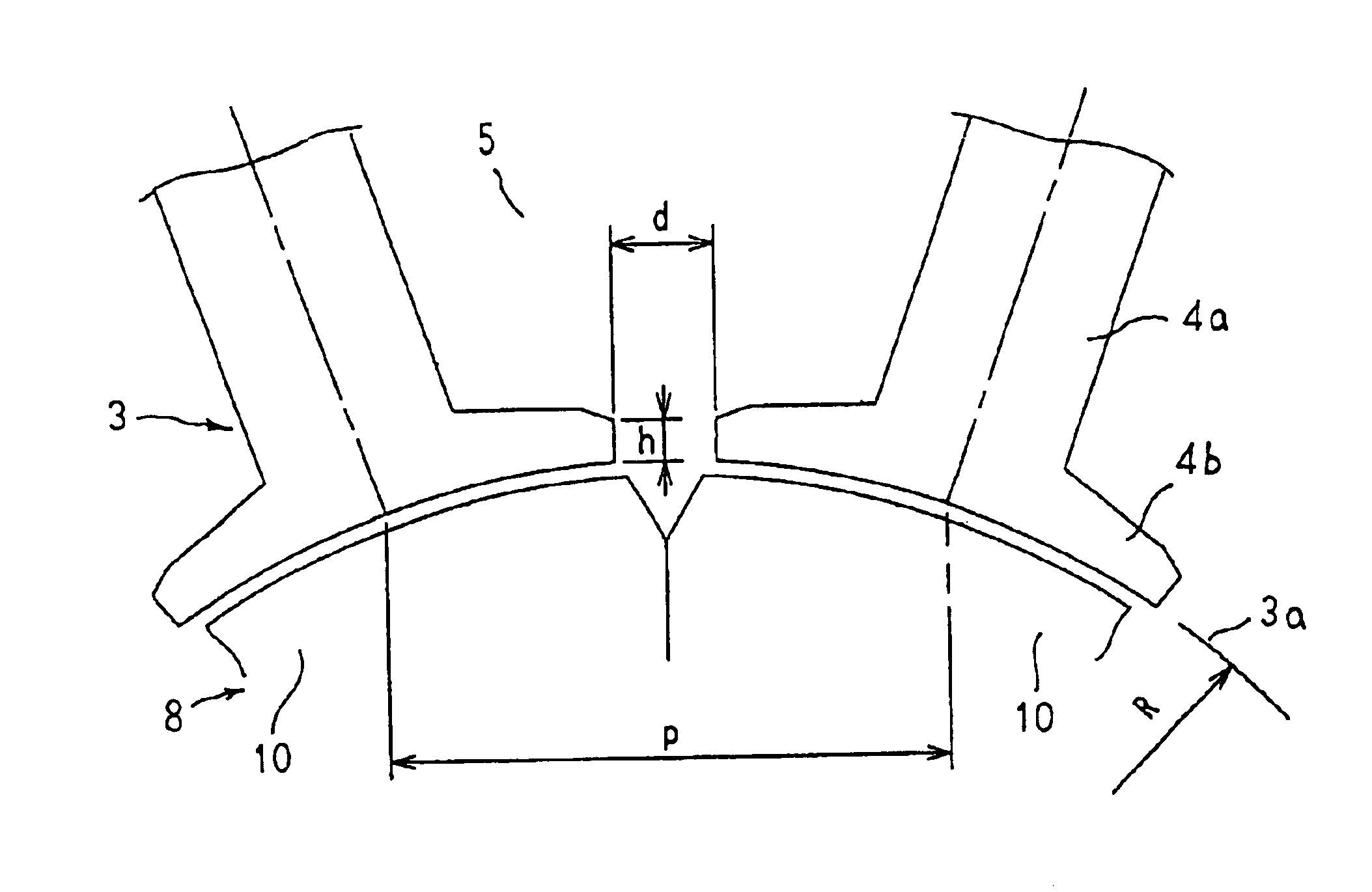
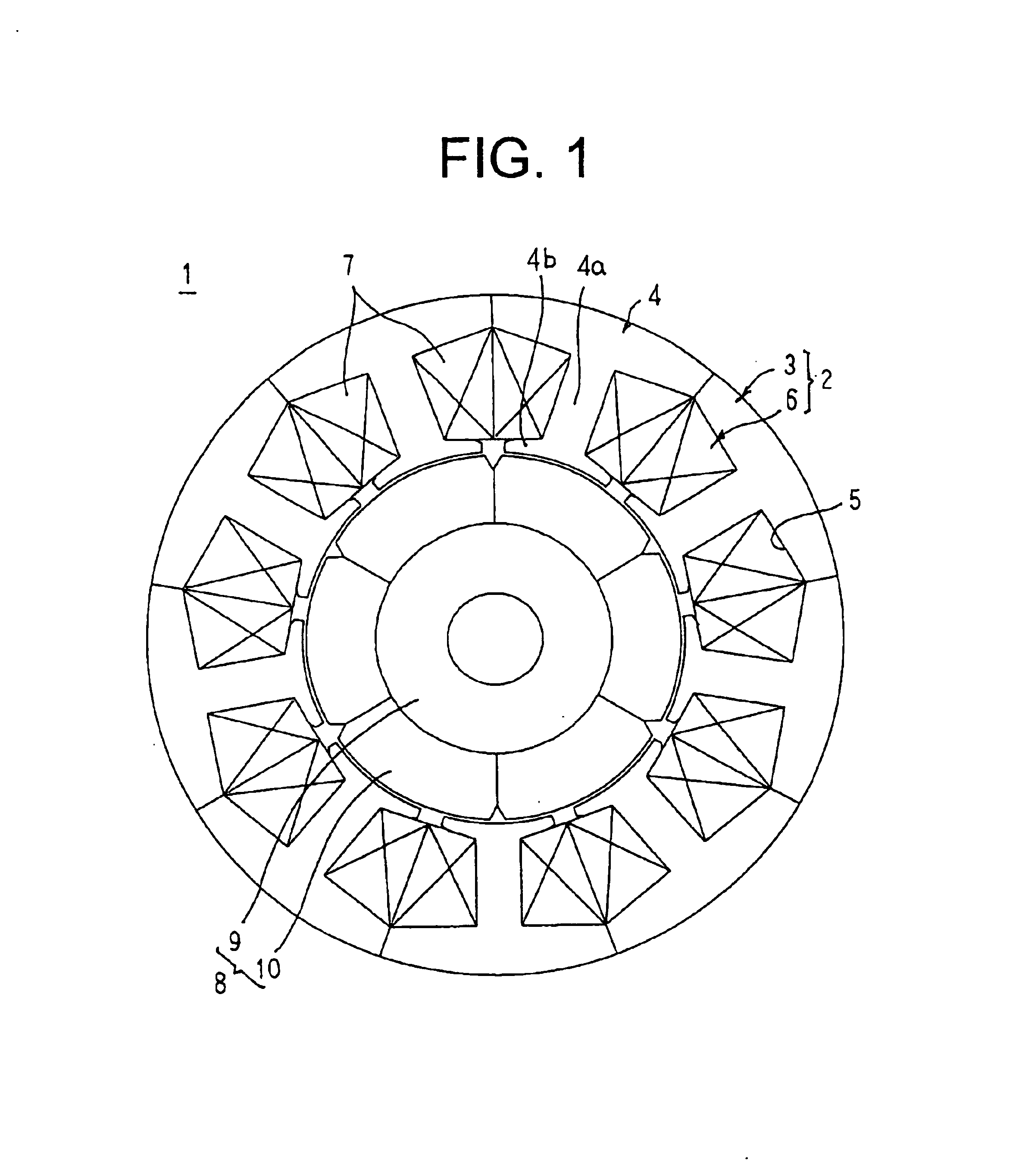
[0026]FIG. 1 is a cross section showing a permanent-magnet synchronous motor according to Embodiment 1 of the present invention, and FIG. 2 is an enlarged cross section showing part of the permanent-magnet synchronous motor according to Embodiment 1 of the present invention.

[0027]In the figures, a concentrated-winding permanent-magnet synchronous motor 1 is constituted by: a stator 2; and a rotor 8 rotatably disposed inside the stator 2.

[0028]The stator 2 is constituted by: a cylindrical stator core 3 having core portions 4 corresponding in number to a number of slots 5; and a stator coil 6 installed in the stator core 3.

[0029]Each of the core portions 4 is constructed by laminating and integrating a predetermined number of sheets of a magnetic material such as a silicon steel sheet, for example. Teeth 4a formed on the core portions 4 are arranged at a uniform angular pitch in a circumferential direction, the slots 5 of the stator core 3 being formed between adjacent pairs of the te...

embodiment 2

[0042]In Embodiment 2, dimensions of the concentrated-winding permanent-magnet synchronous motor 1 according to Embodiment 1 above are set such that 0.2≦h / d≦0.7, where d is a slot opening of the stator core 3 and h is a thickness of an end portion of the flange portions 4b.

[0043]Now, results are shown in FIGS. 6, 7, and 8 in which the torque ratio (percent), the rotational frequency ratio (percent), and the inductance ratio (percent) were measured in a stator core 3 in which the slot pitch p at the inner circumferential surfaces 3a of the stator core 3 was 16.5 mm and the slot opening d was 3.0 mm (d / p=0.182), while h was varied.

[0044]From FIG. 6, it can be seen that when h / d is less than 0.2 (h / d<0.2), the torque ratio increases rapidly as h / d increases, and when h / d exceeds 0.2, the increase in the torque ratio is small. When h / d is equal to or greater than 0.2 (0.2≦h / d), the torque ratio is kept to a high level.

[0045]Thus, because changes in the characteristics of the motor due ...

embodiment 3

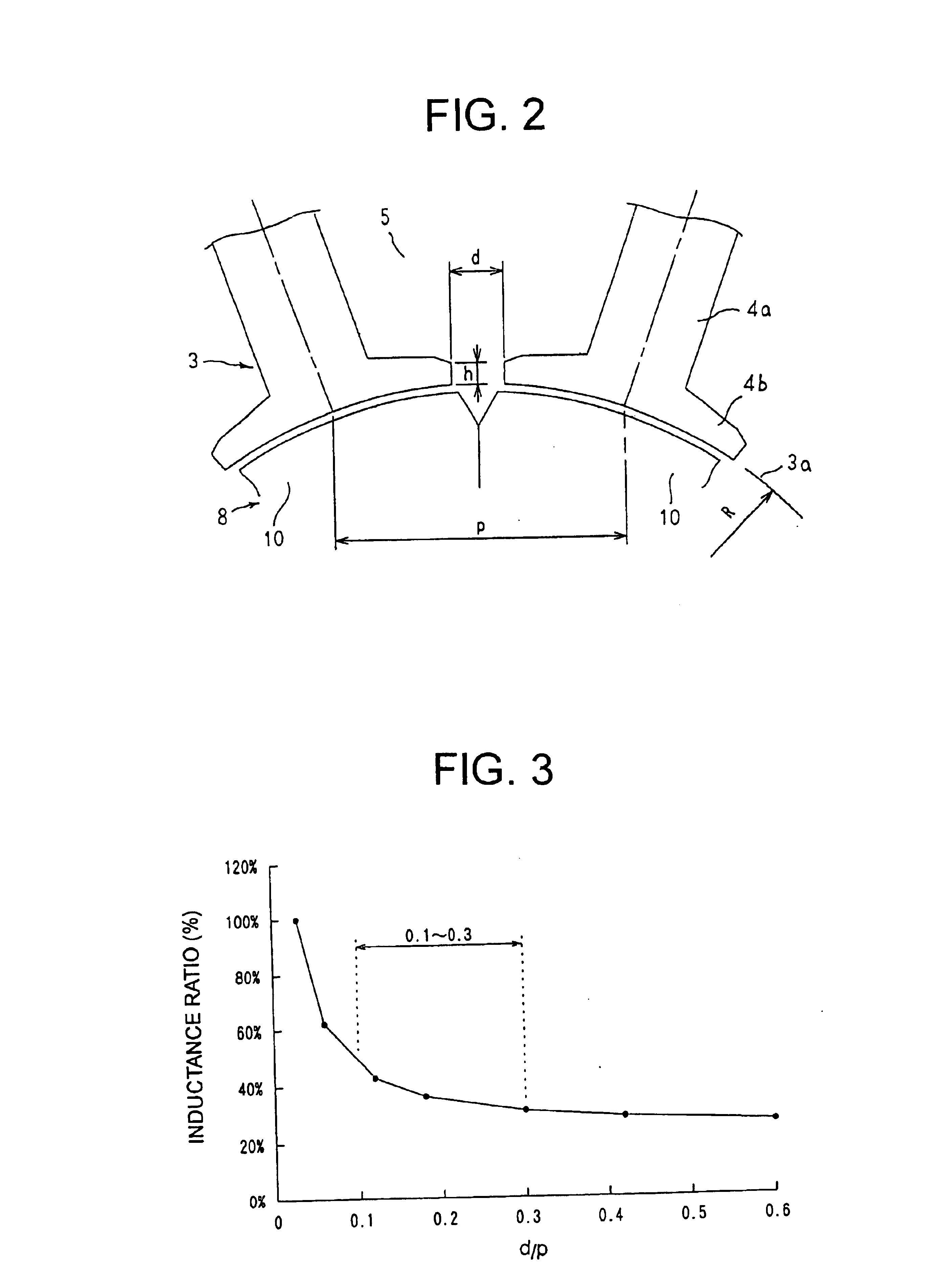
[0051]In Embodiment 3, the concentrated-winding permanent-magnet synchronous motor 1 according to Embodiment 1 above is constructed such that the relationship between the slot opening (d) and the slot pitch (p) and the relationship between the slot opening (d) and the thickness (h) of the end portion of the flange portions 4b in the stator core 3 satisfy the expression 0.1≦d / p≦0.3 and the expression 0.2≦h / d≦0.7, respectively.

[0052]Consequently, according to Embodiment 3, a synergistic combination of the effects of Embodiments 1 and 2 above can be achieved.

[0053]Moreover, each of the above embodiments has been explained with reference to a concentrated-winding permanent-magnet synchronous motor in which the number of magnetic poles in the rotor 8 is six and the number of slots is nine, but it is only necessary for the present invention to be applied to a 3-slot-per-2-pole concentrated-winding permanent-magnet synchronous motor, and for example, similar effects can also be achieved if...


PUM


Abstract

A stator core is formed into a cylindrical shape, 3n teeth are disposed at a predetermined pitch in a circumferential direction where n is a positive integer, and slots are formed between adjacent pairs of the teeth so as to open onto an inner circumferential side. A stator coil is installed as a concentrated winding in the stator core. A rotor is rotatably disposed inside the stator and 2n permanent magnets are disposed at a predetermined pitch in a circumferential direction on an outer peripheral portion of a shaft. The stator core is constructed such that a slot opening (d) and a slot pitch (p) at an inner circumferential surface of the stator core satisfy an expression 0.1≦d/p≦0.3.

Description

BACKGROUND OF THE INVENTION[0001]1. Field of the Invention[0002]The present invention relates to a permanent-magnet synchronous motor in which permanent field magnets are provided in a rotor.[0003]2. Description of the Related Art[0004]Generally, concentrated-winding permanent-magnet synchronous motors are constructed such that 3n teeth of a stator core are disposed at a uniform pitch where n is a positive integer, a stator coil is formed by Y-connecting three phases of coil each wound independently onto the teeth, and 2n permanent magnets are disposed so as to face the stator core. In other words, concentrated-winding permanent-magnet synchronous motors have a 2n-pole permanent magnetic field disposed relative to 3n teeth.[0005]Because a concentrated winding method is adopted in conventional permanent-magnet synchronous motors constructed in this manner, inductance is increased by adjacent teeth forming opposite poles, facilitating the action of demagnetizing fields on the permanen...

Claims


Application Information

Patent Timeline
IPC IPC(8): H02K1/14H02K21/16H02K21/14
CPCH02K21/16H02K1/148
Inventor TANAKA, TOSHINORIMATSUI, YUUSUKEFUKAZAWA, KEIICHIAKUTSU, SATORUFUJIMOTO, KENGOOHATA, KATSUMISUGIYAMA, TAKESHI
Owner MITSUBISHI ELECTRIC CORP
Why Eureka
Try Eureka