Rotating head ellipsometer

a technology of ellipsometry and rotating head, which is applied in the direction of optical radiation measurement, instruments, polarisation-affecting properties, etc., can solve the problems of reducing and broadening the thermal path of the ring design

Inactive Publication Date: 2005-04-19
THERMA WAVE INC
View PDF37 Cites 4 Cited by
  • Summary
  • Abstract
  • Description
  • Claims
  • Application Information

AI Technical Summary

Benefits of technology

[0022]The subject invention allows periodic structures to be measured from a preferred direction while using a reduced motion stage. It should also be noted that this system allows any measurement area to be measured from any direction. While it is generally true that maximum information may be obtained when measuring a periodic structure when the beam is directed perpendicular to the line structure, additional information can be obtained from measurements where the beam is directed parallel to the line structure or even at a 45 degree angle with respect thereto. The subject invention would allow measurements from any desired direction. Such measurements could be used individually or combined in a regression analysis to more fully characterize the structure.

Problems solved by technology

However, such reduced motion stage systems have caused a problem with measuring periodic structures where the impinging direction of the probe beam PB has to correspond to a measurement orientation of the periodic structures PS1, PS2.
Unfortunately, and as seen in FIG. 2B, the result of this rotation is to orient the periodic structure PS2 so that the probe beam impinges thereon in a direction parallel to the lines.
In addition, the ring design reduces and broadens a thermal path for evenly channeling the thermal energy from stator coils onto the immovable portion of the apparatus top.

Method used


Image

  • Rotating head ellipsometer
  • Rotating head ellipsometer
  • Rotating head ellipsometer

Examples


Embodiment Construction

Overview

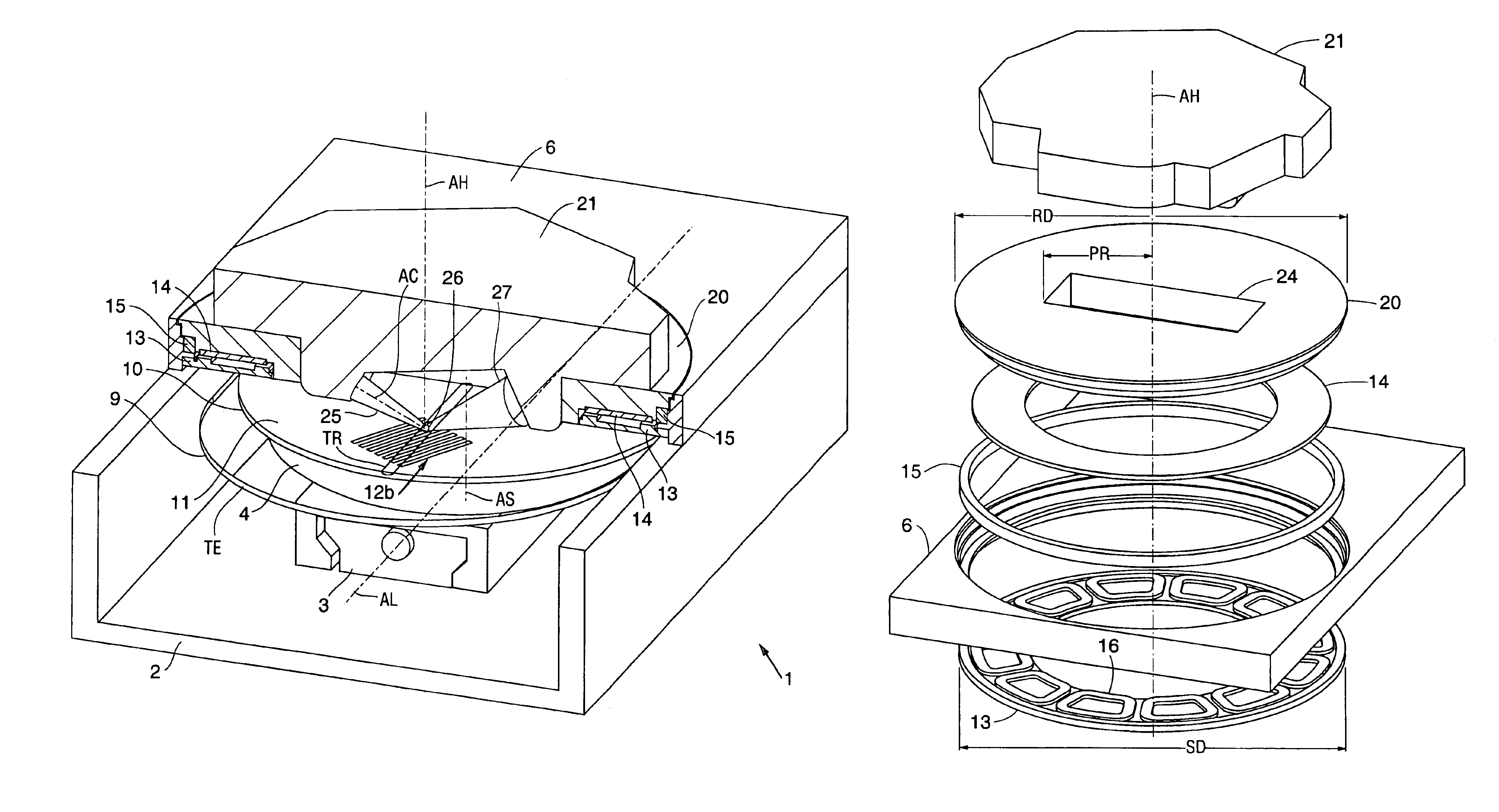
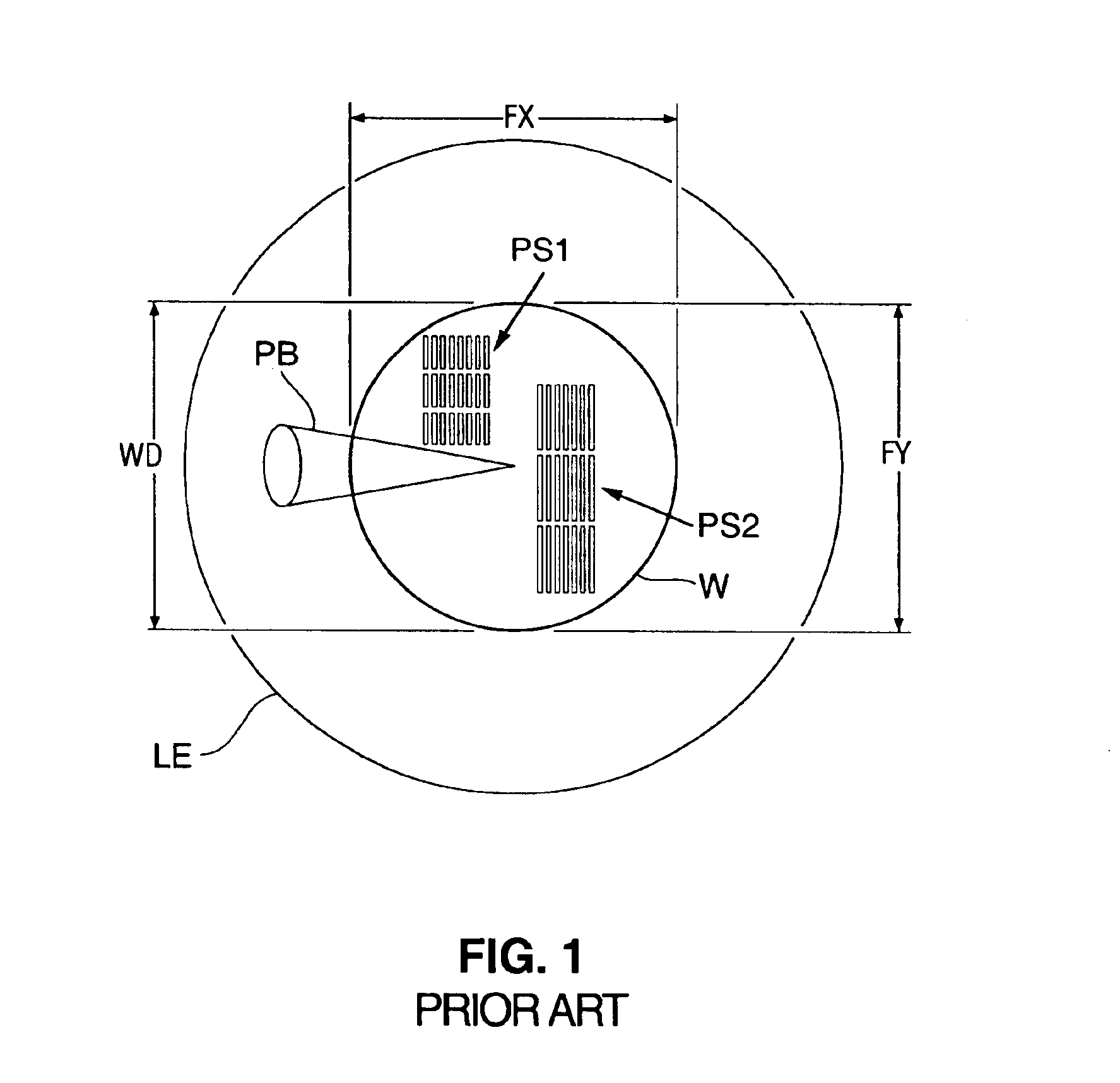
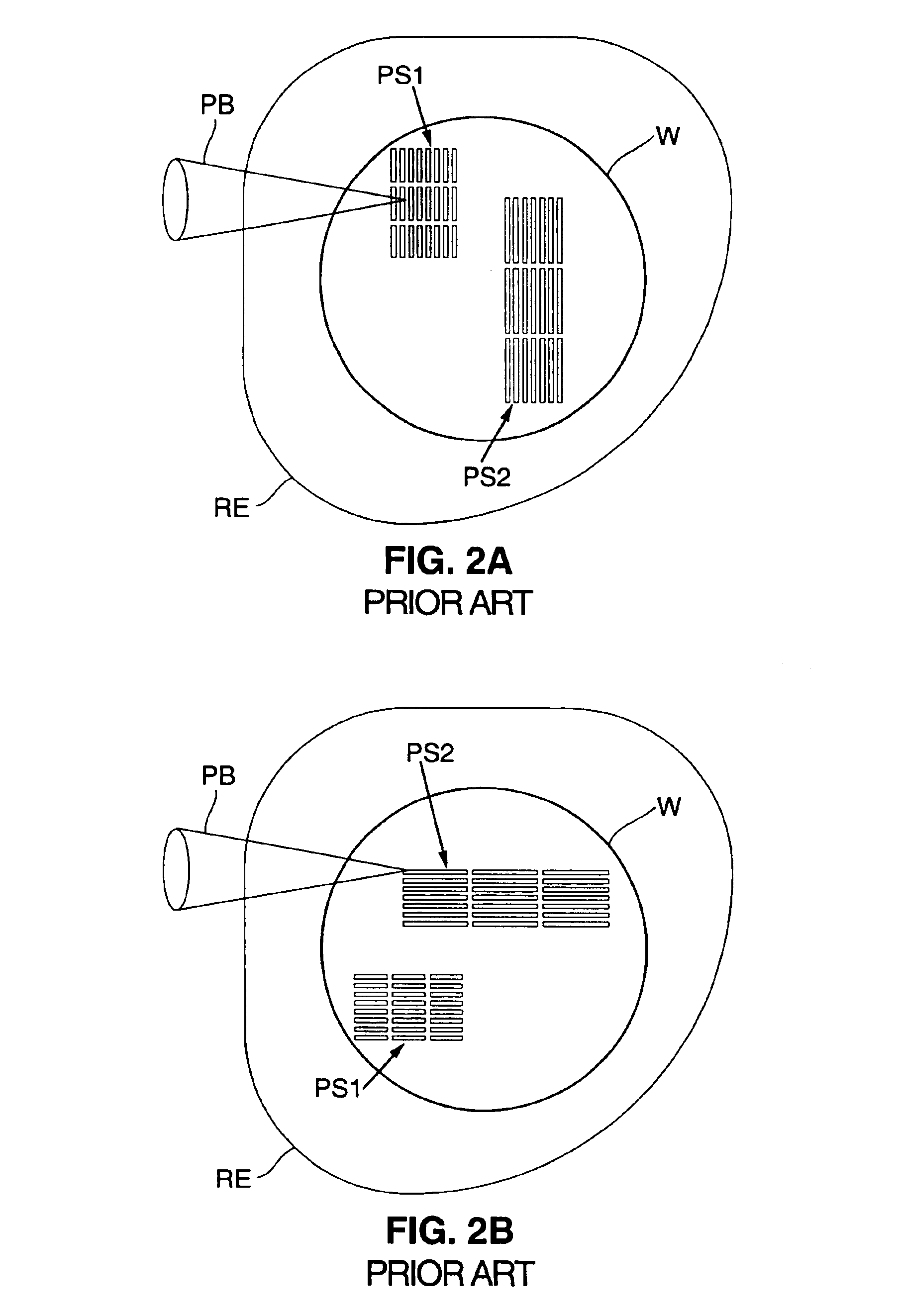
[0033]In the preferred embodiment, the present invention is utilized for performing directional reflectance measurement of a wafer 10 (see FIGS. 3-6) within a minimal footprint of the apparatus 1 (see FIGS. 3, 4). During directional reflectance measurement, surface features 12a, 12b (see FIGS. 3, 5, 6) have to be accessed by a probe beam 25 (see FIGS. 3-6) in an impinging direction that is oriented in conjunction with the orientation of the surface features 12a, 12b. The features 12a, 12b may be located anywhere on the wafer surface 11 and may need to be positioned in a specific orientation for measurement. Thus, in order to perform directional reflectance measurement on essentially the entire wafer surface 11, the direction of the probe beam 25 is rotated in combination with a positioning movement of the wafer 10.

[0034]For accessing a measurement area of a wafer 10, for directional reflectance measurement, three movement qualities need to be provided. In the prior art, thre...


PUM

PropertyMeasurementUnit
impinging angle IAaaaaaaaaaa

Abstract

An ellipsometric apparatus provides a rotating focused probe beam directed to impinge a sample in any direction. A rotating stage rotates the wafer into a linear travel range defined by a single linear axis of a single linear stage. As a result, an entire wafer is accessed for measurement with the single linear stage having a travel range of only half the wafer diameter. The reduced single linear travel results in a small travel envelope occupied by the wafer and consequently in a small footprint of the apparatus. The use of a rotating probe beam permits measurement of periodic structures along a preferred direction while permitting the use of a single reduced motion stage.

Description

PRIORITY[0001]This application claims priority to provisional application Ser. No. 60 / 354,387, filed Feb. 4, 2002, the disclosure of which is incorporated herein by reference.FIELD OF INVENTION[0002]The present invention relates to ellipsometric systems for measuring feature configurations on wafers. Particularly, the present invention relates to a compact ellipsometer useful for measuring features that have a preferential measurement direction.BACKGROUND OF THE INVENTION[0003]Semiconductors are typically fabricated by depositing and etching a number of layers that are shaped and configured on the upper or top surface of a wafer. Controlling those fabrication steps and testing the wafer early during production helps to keep production costs low. An increasingly important technique for a non-destructive measurement of semiconductors is ellipsometry. In ellipsometry, a specifically configured and focused probe light beam is directed to reflect off the wafer. The change in polarization...

Claims


Application Information

Patent Timeline
Patent Type & Authority Patents(United States)
IPC IPC(8): G01N21/21
CPCG01N21/211
Inventor BOWMAN, BARRY R.
Owner THERMA WAVE INC
Why Eureka
Try Eureka