Coherent power combining of single-mode sources in waveguide fiber couplers

a waveguide fiber coupler and waveguide technology, applied in the field of optical power amplification, can solve the problems of extreme difficulty in getting with conventional power combining schemes, and achieve the effects of optical power scaling, reducing power consumption, and maintaining beam quality

Inactive Publication Date: 2005-04-19
HRL LAB
View PDF11 Cites 43 Cited by
  • Summary
  • Abstract
  • Description
  • Claims
  • Application Information

AI Technical Summary

Benefits of technology

[0008]It is an object of the present invention to enable optical power scaling using a plurality of relatively low-power amplifiers while maintaining beam quality. It is a further object of the present invention to coherently combine the outputs of the plurality of relatively low-power, fiber amplifiers in a power scaling system that provides either higher output power or equal output power, and has a longer lifetime than systems that use high power amplifiers.
[0009]One embodiment of the present invention combines the output energies of a plurality of optical channels that comprise relatively low-power, fiber amplifiers into a single diffraction-limited spot by coherently combining the output of multiple fiber amplifiers in waveguide couplers, such as 3 dB fiber couplers. The coherent combination of the output energy in the fiber preserves the mode quality of the initial beam. In addition, the coherent combining in waveguide couplers allows not just the intensities of the optical signals to be summed, but the electric fields as well, providing for an output beam that can be focused to a smaller spot beam than is available through other power combining methods. Hence, power scaling of relatively low-power and thus reliable fiber amplifiers is accomplished while retaining beam quality, which is extremely difficult to get with conventional power combining schemes.

Problems solved by technology

Hence, power scaling of relatively low-power and thus reliable fiber amplifiers is accomplished while retaining beam quality, which is extremely difficult to get with conventional power combining schemes.

Method used


Image

  • Coherent power combining of single-mode sources in waveguide fiber couplers
  • Coherent power combining of single-mode sources in waveguide fiber couplers
  • Coherent power combining of single-mode sources in waveguide fiber couplers

Examples


Embodiment Construction

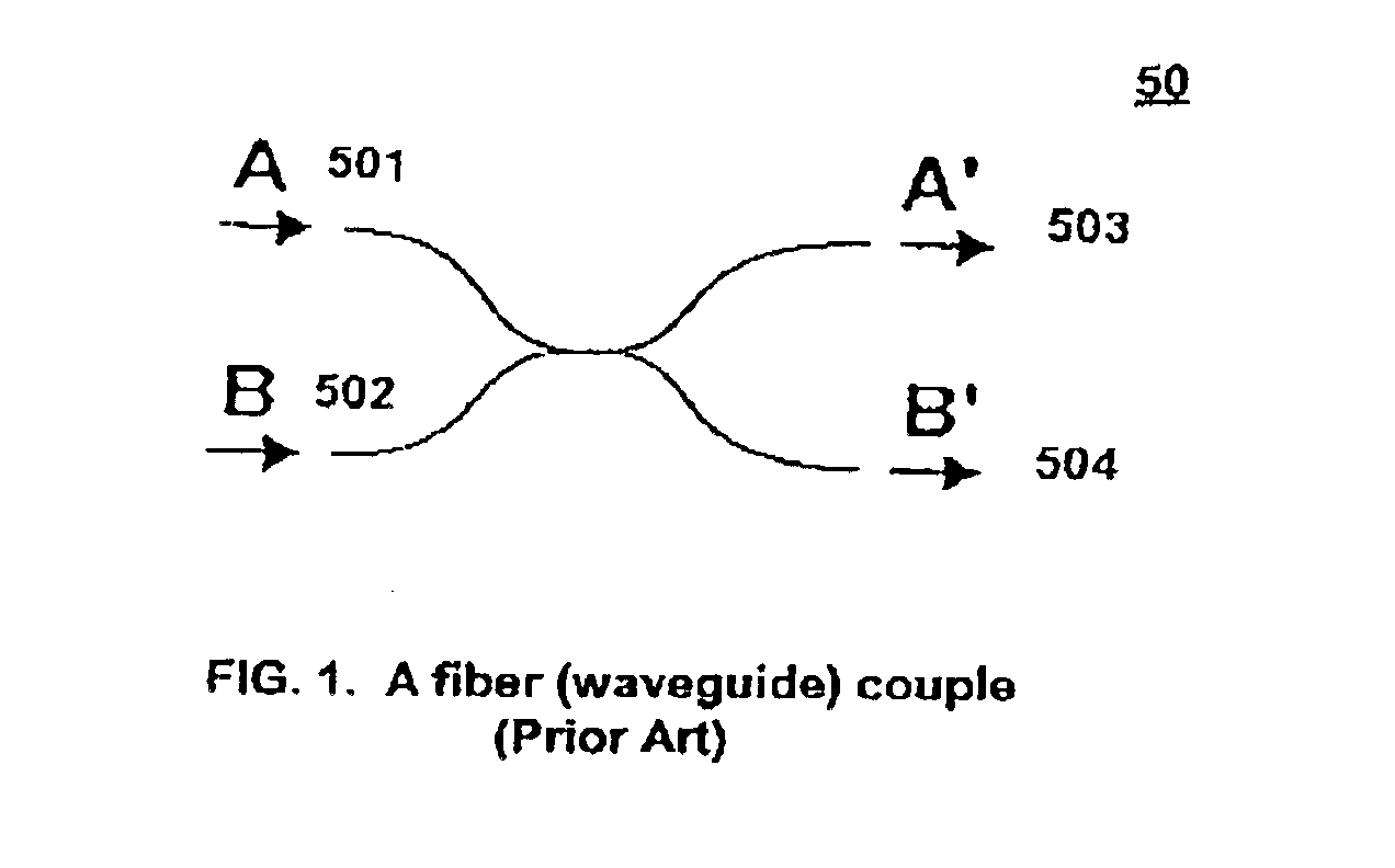
[0018]FIG. 1 depicts a fiber or waveguide coupler as known in the prior art. The operational principle of the present invention is based on well known properties of fiber (or waveguide) couplers as can be found in H. A. Haus, “Waves and Fields in Optoelectonics,” Prentice-Hall, Englewood Cliffs, 1984, pp. 217-220. The amplitudes of output optical waves exciting a coupler made of identical fibers or waveguides are given, respectively by the formulas A′=[A⁢ ⁢cos⁢ ⁢(|κ12|z)+κ12|κ12|⁢B⁢ ⁢sin⁡(|κ12|z)]⁢ ⁢ⅇ⁢ ⅈ⁢ ⁢β⁢ ⁢c⁢⁢B′=[κ21|κ12|⁢A⁢ ⁢sin⁡(|κ12|z)+B⁢ ⁢cos⁡(|κ12|z)]⁢ ⁢ⅇ⁢ -ⅈ⁢ ⁢β⁢ ⁢c(1)

where A and B are complex amplitudes for the corresponding input waves, z is the length of the coupling region, κ12 and κ21 are complex coupling constants with κ12=κ*21, and β is the propagation wavenumber, which is assumed to be the same in both waveguides. In 3 dB, (i.e., 50×50 couplers), κ12z=[πeiφ] / 4, where φ may take on any value. For illustrative purposes we assume φ=0. Other values of φ require differe...


PUM


Abstract

An optical power combining system. The system may comprise: a means for splitting an optical source into multiple channels; amplifiers in the multiple channels; and waveguide couplers for coherently combining the multiple channels into a single output.

Description

CROSS-REFERENCES TO RELATED APPLICATIONSCLAIM OF BENEFITS OF PROVISIONAL APPLICATION[0001]Applicants claim the benefits of their United States Provisional application Ser. No. 60 / 332,575, filed on 16 Nov. 2001 now abandoned.[0002]The present document is related to the co-pending and commonly assigned U.S. patent application Ser. No. 09 / 574,282 filed May 19, 2000, which is hereby incorporated herein by reference.TECHNICAL FIELD[0003]This invention relates to optical power amplification. In particular, it relates to power amplification using optical couplers through coherent combination of amplified signals.BACKGROUND OF THE INVENTION[0004]Optical power amplification has relevance to terrestrial and space applications. A well-known terrestrial application requiring optical power amplification is laser radars for missiles. A well-known space application requiring optical power amplification is inter-satellite optical communications. Such applications may require optical power outputs a...

Claims


Application Information

Patent Timeline
Patent Type & Authority Patents(United States)
IPC IPC(8): H01S3/06H01S3/067H01S3/23G02B6/28H01S5/40H01S5/50H01S5/00
CPCH01S3/06754H01S3/2383G02B6/2804H01S5/50H01S5/4012H01S5/4025
Inventor IONOV, STANISLAV I.
Owner HRL LAB
Why Eureka
Try Eureka