Pulse detonation engine having an aerodynamic valve

a technology of aerodynamic valve and propellant, which is applied in the direction of intermittent jet plants, combustion types, lighting and heating apparatus, etc., can solve the problems of loss of efficiency, difficult and/or impractical implementation in this application and environment, and each has significant limitations, so as to optimize the specific impulse or thrust, accelerate the combustion of the injected propellant, and maximize performance

Inactive Publication Date: 2005-04-26
UNITED TECH CORP
View PDF11 Cites 40 Cited by
  • Summary
  • Abstract
  • Description
  • Claims
  • Application Information

AI Technical Summary

Benefits of technology

[0011]A pulse detonation engine (PDE) is provided with an aerodynamic valve (aerovalve) for controlling the pressure of injected fluids, typically gases, but also including liquids, such as fuel or fuel and oxidizer, referred to as propellants, in an open-ended detonation chamber. The PDE includes a detonation chamber closed at a thrust wall end and open at the opposite, exhaust, end. A fluid injection mechanism injects pressurized propellant fluid into and directed toward the thrust wall end of, the detonation chamber. The propellant fluid is injected in a pulsed manner by the injection mechanism, and with sufficient pressure and velocity and such direction as to effectively restrict or prevent rearward flow of the injected fluid, thus forming a closed aerovalve. Moreover, the injected propellant fluid establishes a shock wave which, when moving rearward in the detonation chamber toward the exhaust end after reflection by the thrust wall end, serves in combination with the closed aerovalve to increase, or at least sufficiently conserve, the pressure of the fluid in the chamber, such that it is a pressure preferably greater than, or at least nearly as great as, that at which it ent

Problems solved by technology

Two alternative concepts that may be used to control chamber pressure are mechanical valves and fixed throats, but each has significant limitations.
The complexity and weight of a mechanical valve, combined with durability and sealing requirements in the hot exhaust flow, s

Method used


Image

  • Pulse detonation engine having an aerodynamic valve
  • Pulse detonation engine having an aerodynamic valve
  • Pulse detonation engine having an aerodynamic valve

Examples


Embodiment Construction

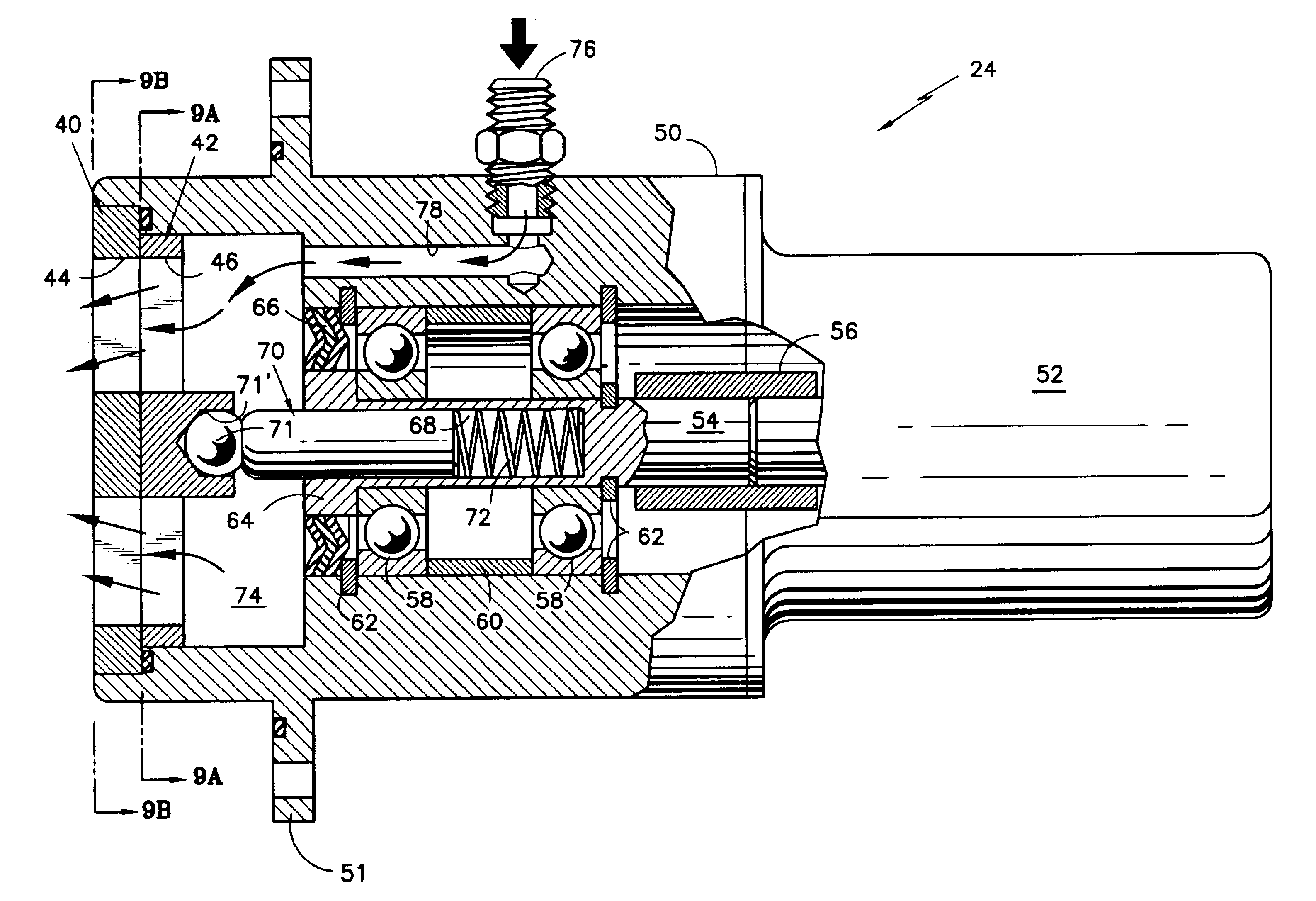
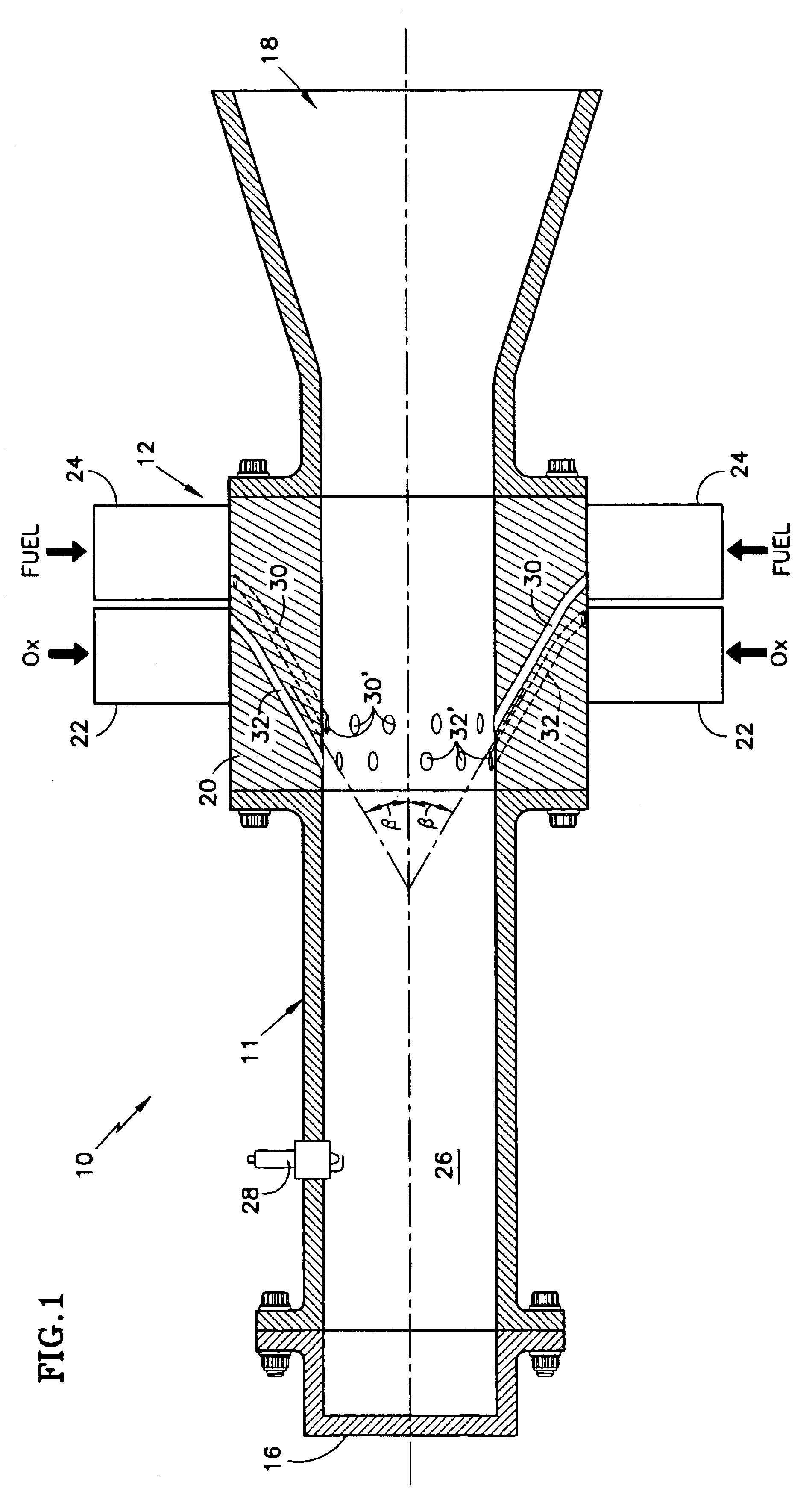
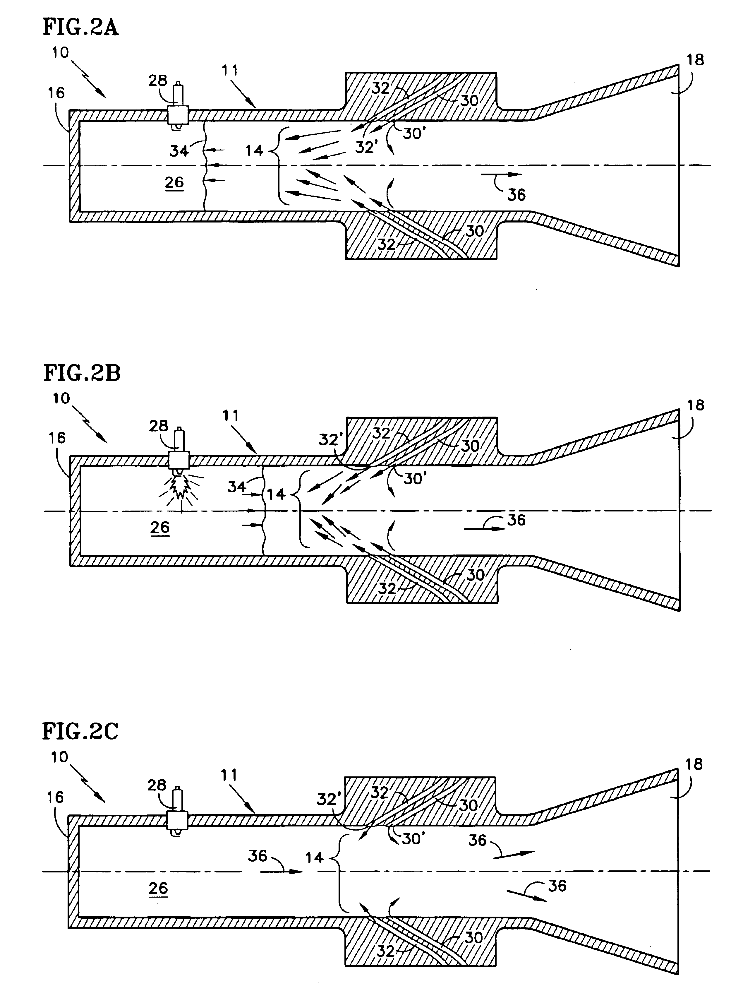
[0029]Referring to FIGS. 1 and 2A-2C, there is illustrated in FIG. 1 a simplified, somewhat diagrammatic, cross-sectional view of a pulse detonation engine (PDE) 10 employing fluid injection mechanism 12 to provide the aerodynamic valve (aerovalve) 14 depicted diagrammatically through the use of gas flow arrows in FIGS. 2A-2C in accordance with the invention. The PDE 10 is typically an elongate tubular structure 11 having a closed thrust wall end 16 and an opposite exit, or exhaust, end 18 that is open. A fluid injection mechanism 12 is located intermediate the opposite ends 16 and 18, relatively toward the exhaust end 18, and may typically include an annular injector member 20 and associated fluid pulse injection valves 22 and 24. The annular injector member 20 may conveniently be included as a structural portion of the tubular PDE structure. The region of the PDE between the injector member 20 and the thrust wall end 16 comprises the detonation, or combustion, chamber 26. An activ...


PUM


Abstract

A pulse detonation engine (10) is provided with an aerovalve (14) for controlling the pressure of injected propellants (Ox, Fuel) in an open-ended detonation chamber (26). The propellants are injected at such pressure and velocity, and in a direction generally toward a forward thrust wall end (16) of the detonation chamber (26), an aerovalve (14) is formed which effectively inhibits or prevents egress of the propellant from the detonation chamber (26). A shock wave (34) formed by the injected propellant acts, after reflection by the thrust wall end (16) and in combination with the aerovalve (14), to compress and conserve, or increase, the pressure of the injected propellant. Carefully timed ignition (28) effects a detonation pulse under desired conditions of maintained, or increased, pressure. Termination of the propellant injection serves to “open” the aerovalve (14), and exhaust of the combusted propellants occurs to produce thrust. Alternate embodiments of propellant injection mechanisms (12, 112) provide pulse valves (24, 122, 124) each having a fixed slotted disk (40, 140, 240) and a rotating slotted disk (42, 142, 242) to provide the desired high speed valving of discrete pulses of propellant for injection.

Description

[0001]This application is a division of U.S. patent application Ser. No. 10 / 026,236, filed Dec. 21, 2001 now U.S. Pat. No. 6,584,765 and incorporated herein by reference.[0002]This invention was made with United States Government support under Contract Number NAS8-98-035 awarded by the National Aeronautics and Space Administration. The Government has certain rights in this invention.TECHNICAL FIELD[0003]This invention relates generally to pulse detonation engines, and more particularly to the fluid dynamics of such engines. More particularly still, the invention relates to the valving of fluids employed in pulse detonation engines.BACKGROUND ART[0004]Pulse detonation engines (PDE) represent an energy conversion device that has existed for some time, but which have recently received increased attention. Such engines generally combust fuel and an oxidant in a chamber, or combustor, to provide a component of thrust or force in an intended direction. The combustion occurs in the manner ...

Claims


Application Information

Patent Timeline
IPC IPC(8): B64G1/40B64G1/22F02K7/06F02K7/067F02K7/00F23C15/00
CPCB64G1/401B64G1/402F02K7/06F02K7/067F23C15/00Y02T50/671F23C2205/10F23C2205/20Y02T50/67Y02T50/60Y10T137/86405Y10T137/86743
Inventor TEW, DAVID E.TWELVES, JR., WENDELL V.
Owner UNITED TECH CORP
Why Eureka
Try Eureka