Automatic debris separation system

a technology of automatic separation and debris, applied in the direction of solid separation, gas current separation, agriculture tools and machines, etc., can solve the problems of preventing the recovery of useful components, requiring constant challenge from textile manufacturers and suppliers, and merely discarding textile wastes

a technology of automatic separation and debris, applied in the direction of solid separation, gas current separation, agriculture tools and machines, etc., can solve the problems of preventing the recovery of useful components, requiring constant challenge from textile manufacturers and suppliers, and merely discarding textile wastes

US6883667B1Inactive Publication Date: 2005-04-26WELLMAN PLASTICS RECYCLING

Image

  • Automatic debris separation system
  • Automatic debris separation system

Examples


Embodiment Construction

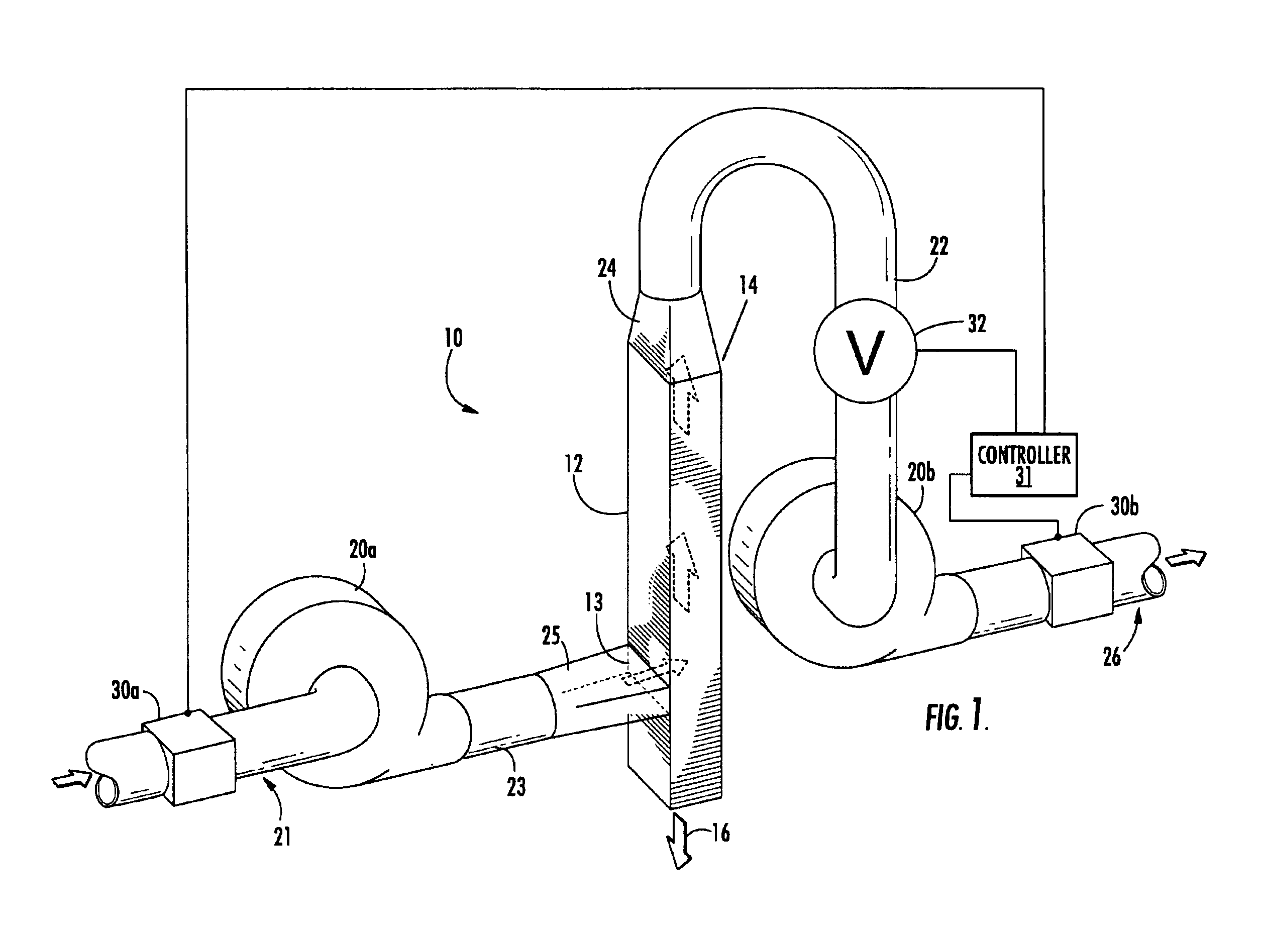
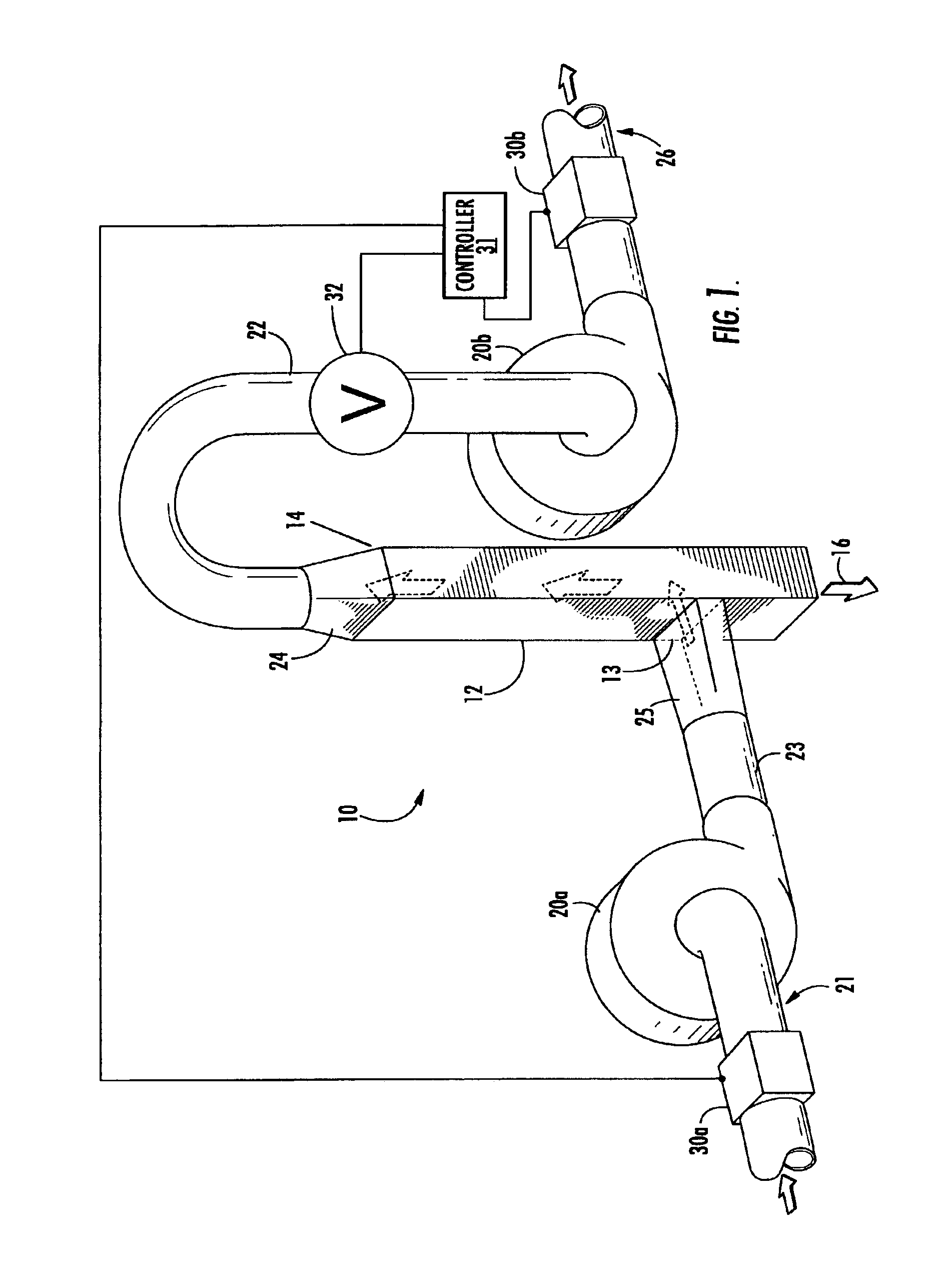
[0017]The present invention is an automatic debris separation system and process for effecting density separation of fragmented materials. This automatic debris separation system is especially well-suited for removing metal debris from intermediate polymer feedstocks, such as those resulting from the reclamation of carpet, yarns, and other textile wastes. Such feedstocks typically include metal debris that must be removed to preclude process upsets during polymer reclamation operations.

[0018]The automatic debris separation system efficiently removes metal contaminants (e.g., wire, staples, rivets, tacks, or baling wire and bands) from reusable polymer fibers (e.g., polyester and nylon). Among other uses, the recovered polymer fibers may be melt-extruded and pelletized, or formed into filaments, such as via melt-spinning. Pelletized polyester and nylon are especially useful for engineering plastics or resins. In this regard, metal debris is an unacceptable defect in most engineering ...


PUM


Abstract

The invention is an automatic debris separation system for effecting air separation of fragmented materials, such as size-reduced fiber feedstocks derived from textile wastes. The system uses high-velocity air within an elutriation assembly to efficiently remove ferrous and non-ferrous metal debris from recyclable polymer fibers. In particular, the system may employ automatic process control strategies to vary airflow within the elutriation assembly in process-controlled response to measured metal contamination, thereby ensuring that post-separation metal contamination is maintained at or below an upper contamination limit.

Description

CROSS-REFERENCE TO RELATED APPLICATION[0001]This application is related to commonly-assigned, concurrently-filed application Ser. No. 10 / 365,015 for a Method of Automatic Debris Separation, which is hereby incorporated entirely herein by reference.BACKGROUND OF THE INVENTION[0002]The invention relates to the efficient and cost-effective recovery of component materials from an unsorted or contaminated feedstock. The invention is especially useful for recovering polymeric material by removing metal debris from polymer fiber feedstocks, such as from textile wastes.[0003]Textile manufacturers and suppliers are continually challenged by the generation of textile waste, such as waste carpet. Each year, large quantities of textile wastes are simply landfilled. Disposing of textile wastes in this way is not only expensive, but also runs counter to increasing corporate emphasis on environmental stewardship. In short, merely discarding textile wastes precludes the recovery of useful component...

Claims


Application Information

Patent Timeline
26 Apr 2005
Publication
US6883667B1
CPC
B07B4/02; B07B11/04; B07B7/01
Inventors
LINDSEY, JAMES A.; ALLEN, JR., DANIEL A.