Temporary and semi-permanent dental crowns

Inactive Publication Date: 2005-04-26
NANOCROWNS TECH
View PDF18 Cites 38 Cited by
  • Summary
  • Abstract
  • Description
  • Claims
  • Application Information

AI Technical Summary

Benefits of technology

[0027]The crown form is optionally provided with at least one aperture in the bite layer of the crown form. In crown forms for molars and bicuspids, the aperture is preferably located on the cusp tips. In crown forms for canines and incisors, the apertures are preferably located on a lingual surface in the vicinity of a junction of the lingual, incisal and neighbour planes. In this manner, the apertures function as vents for expulsion of air during fitting of the temporary crown. Expulsion of air ensures that there is good contact between the crown form and the resin filler and ensures that the product is aesthetically pleasing. The apertures

Problems solved by technology

The polymerization process is exothermic, and therefore can be irritating to the patient unless great care is taken.
However, these temporary adhesives do not adhere to the crown form.
Grinding through the crown form can result in distortion of the crown form

Method used


Image

  • Temporary and semi-permanent dental crowns
  • Temporary and semi-permanent dental crowns
  • Temporary and semi-permanent dental crowns

Examples


Example

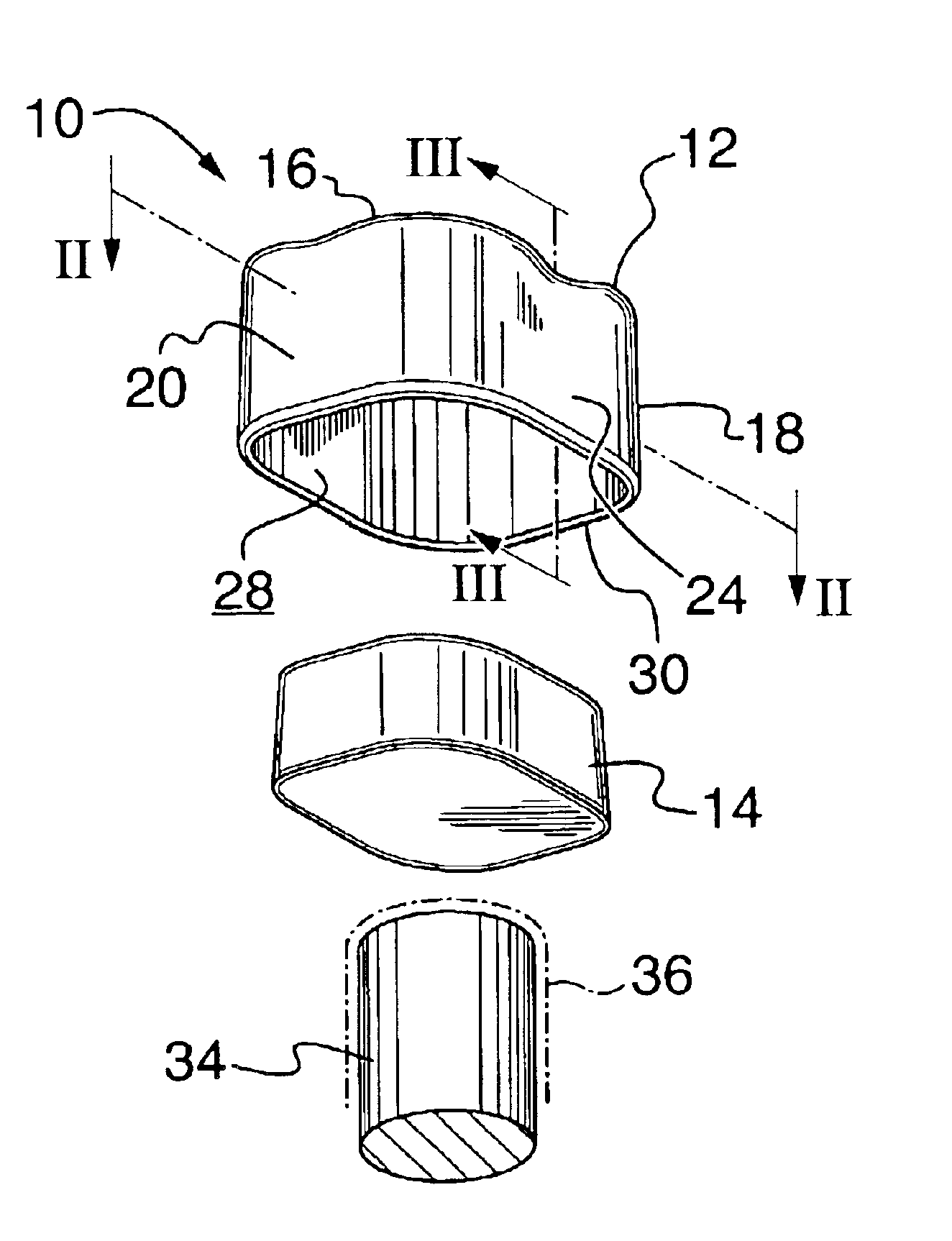
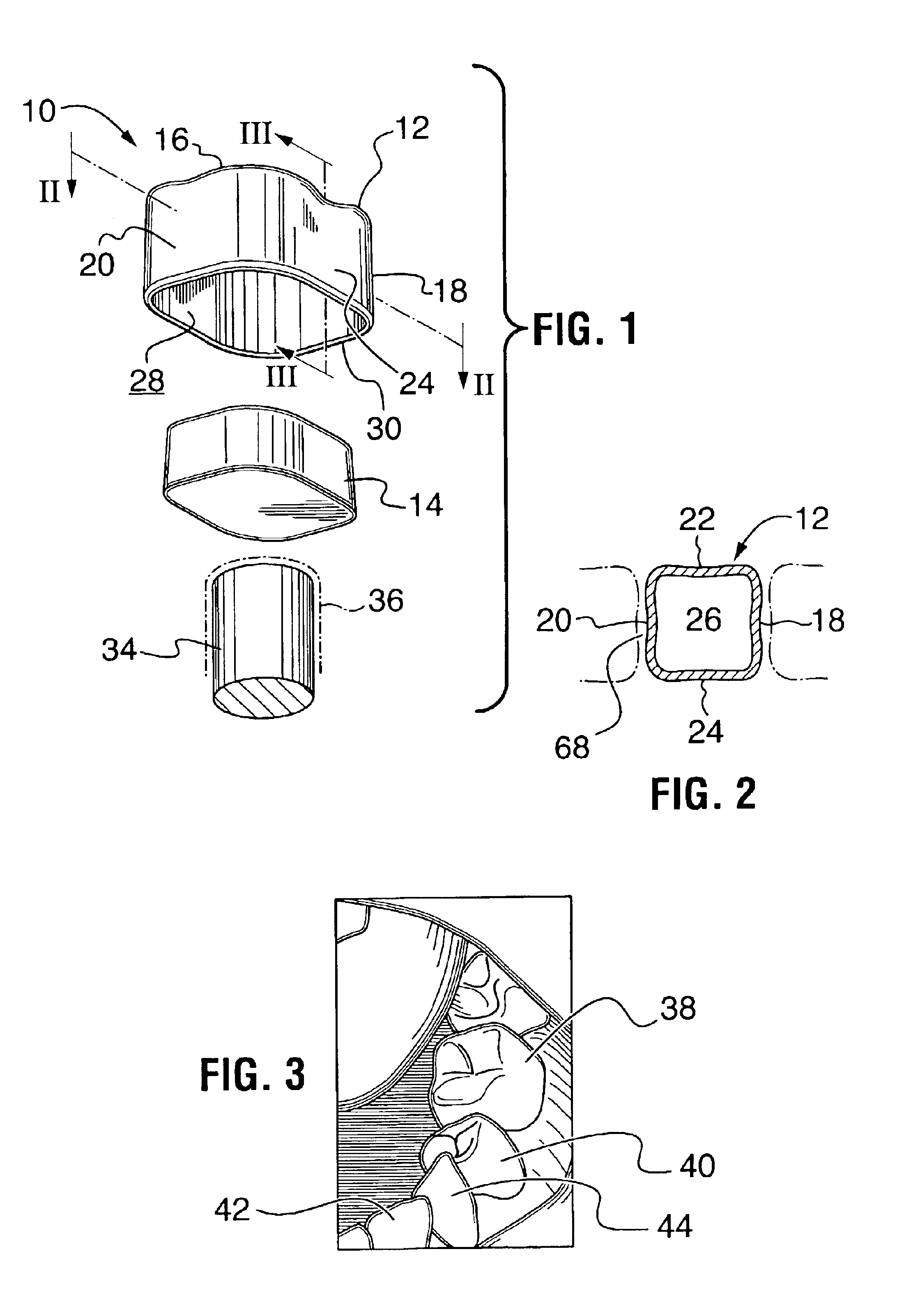
[0053]A temporary crown, generally indicated by the reference number 10, has a crown form 12 and a resin filler 14 (FIG. 1 and 2). The crown form 12 has a bite layer 16 that is integral with two neighbour walls 18, 20, a lingual wall 22 and a buccal wall 24 to define a cavity 26. The walls 18, 20, 22 and 24 have a gingival margin 30 distal to the bite layer 16. The cavity 26 accepts a tooth stub 34 and the resin filler 14 fills a void (not shown) between an inner surface 28 of the crown form 12 and the tooth stub 34. A temporary adhesive 36 is optionally applied to the crown form 12. Additionally, a color dye (not shown) is optionally applied to the inner surface 28 of the crown form 12 in order to color the temporary crown 10.

[0054]There can be a number of different types of temporary crowns 10, depending whether a molar 38, a bicuspid 40, an incisor 42 or a canine 44 is to be crowned (FIG. 3). Further, there are different shapes and sizes of temporary crowns 10, ranging in size fr...


PUM


Abstract

A temporary crown, and variants thereof, including temporary bite caps and temporary facings, comprised of a shaped provisional (crown forms, onlays, veneers and variants thereof) and a resin filler; and a kit of provisionals, resin and auxiliary materials. The provisional has at least a partial bite layer that is integral with two opposing neighbor walls, a lingual wall and a buccal wall which, together, define a cavity to accept a tooth stub, the resin filler and optionally, a temporary adhesive. The resin filler is initially plastic and fills a void between the provisional and the tooth stub. The provisional and resin filler are selected for compatibility and cooperative curability such that following a suitable curing step, the inner layer of the provisional and the resin filler are substantially bound to and integral with one another. The provisional may have apertures through the bite layer and slits through the neighbor walls. The apertures are located in the vicinity of the cusp tips in temporaries for molars and bicuspids and in the vicinity of the junction of the lingual and incisal planes on the lingual surface in temporaries for canines and incisors. A temporary bridge can be formed in situ from a plurality of temporaries.

Description

[0001]This application claims the benefit of Provisional application Ser. No. 60 / 376,210, filed Apr. 30, 2002.BACKGROUND OF THE INVENTION[0002]Permanent crowns, permanent facings and permanent bite caps have been used for many years to replace damaged or decayed teeth. They are also used to improve the aesthetics of teeth, even in cases where there is no damage or decay. The restorative process involves a number of steps. During the restorative process, a dentist must remove the damaged or decayed portion of the tooth, protect the remaining portion of the natural tooth (in the most severe case, a tooth stub) with a temporary (a “temporary” being one of a temporary crown, temporary facing or temporary bite cap) and then later, after a permanent crown, facing or bite cap has been made, restore the tooth by applying the permanent structure to the remaining portion of the natural tooth.[0003]For the purposes of this specification, the remaining portion of the natural tooth will be refer...

Claims


Application Information

Patent Timeline
IPC IPC(8): A61C5/08A61C13/00
CPCA61C5/08A61C5/002A61C13/0001A61C5/20A61C5/30A61C5/70
Inventor CHILIBECK, RICHARD H.
Owner NANOCROWNS TECH
Why Eureka
Try Eureka