Dimpled golf ball and dimple distributing method

a golf ball and dimple technology, applied in the field of golf ball dimple distribution, can solve the problems of golf balls having variations in flight performance, golf balls not being used as a tool to develop and define dimple patterns or optimal dimple distributions, and golf balls not having optimal dimple positioning or distribution for improving aerodynamic performance. , to achieve the effect of improving aerodynamic performan

Inactive Publication Date: 2005-04-26
ACUSHNET CO
View PDF31 Cites 9 Cited by
  • Summary
  • Abstract
  • Description
  • Claims
  • Application Information

AI Technical Summary

Benefits of technology

[0011]One benefit from using these principles to develop dimple patterns is that doing so may result in a golf ball having improved aerodynamic performance.

Problems solved by technology

While the task of distributing point charges on a spherical surface has been studied extensively in mathematical circles, it has not been employed as a tool to develop and define dimple patterns or optimal dimple distributions on a golf ball.
While this approach may be effective in enabling easy dimple design and mold manufacture, it may not result in optimal dimple positioning or distribution for improved aerodynamic performance.
In addition, this approach to designing a dimple pattern may result in a golf ball having variations in flight performance depending upon the direction of rotation of the ball.
The potential limitations described above may be present in other methods for arranging dimples on a golf ball.

Method used


Image

  • Dimpled golf ball and dimple distributing method
  • Dimpled golf ball and dimple distributing method
  • Dimpled golf ball and dimple distributing method

Examples


example 1

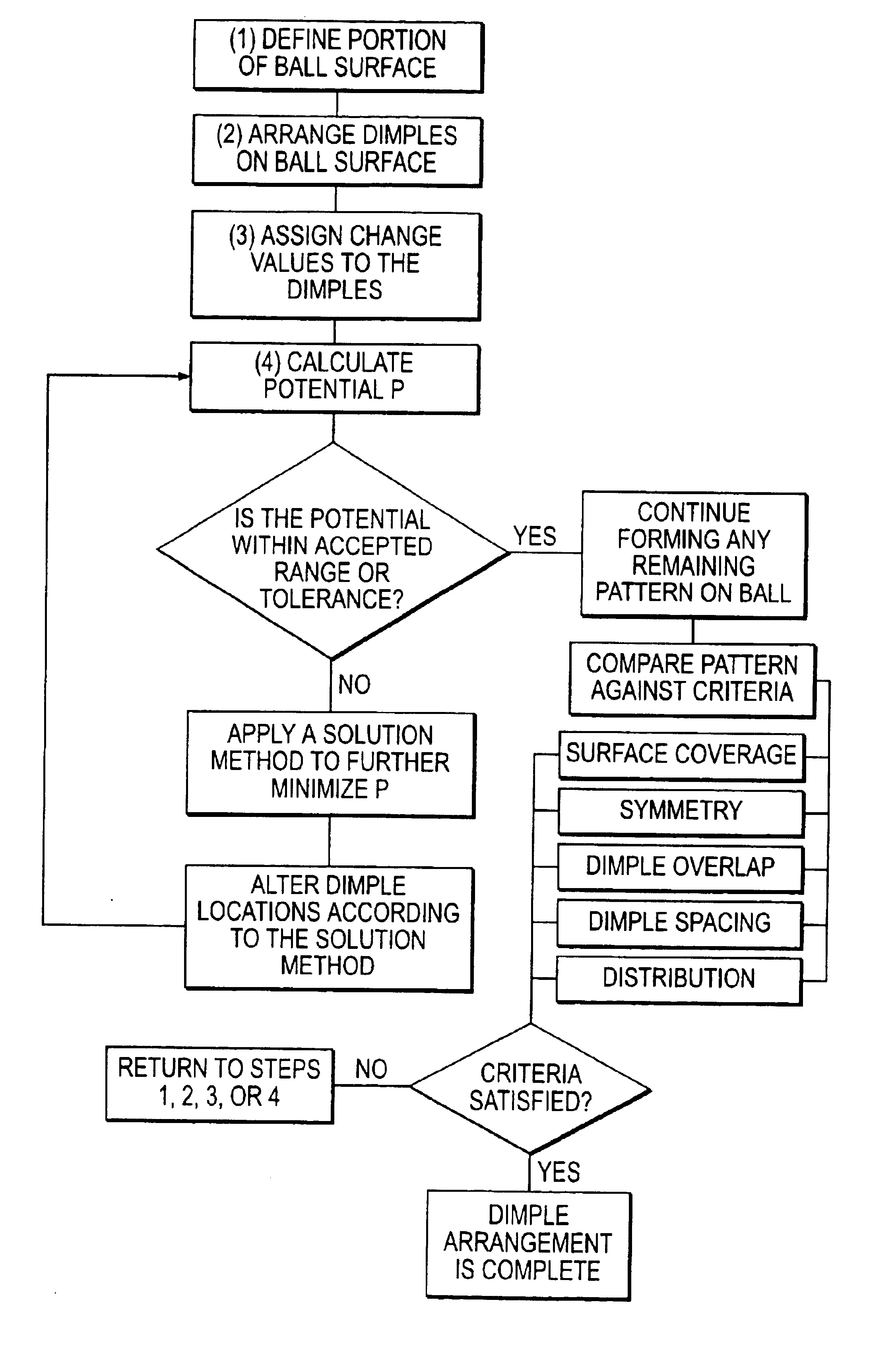
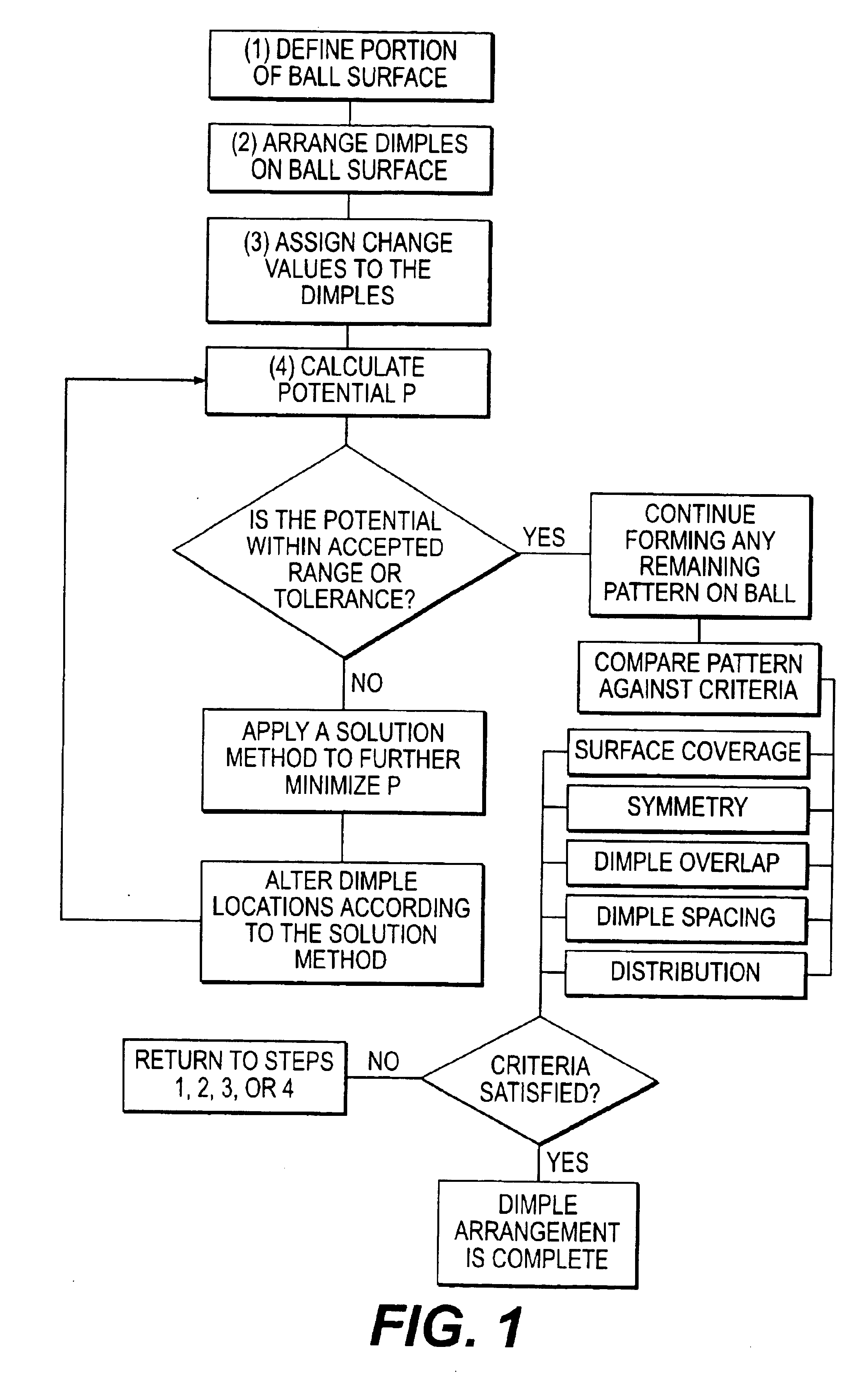
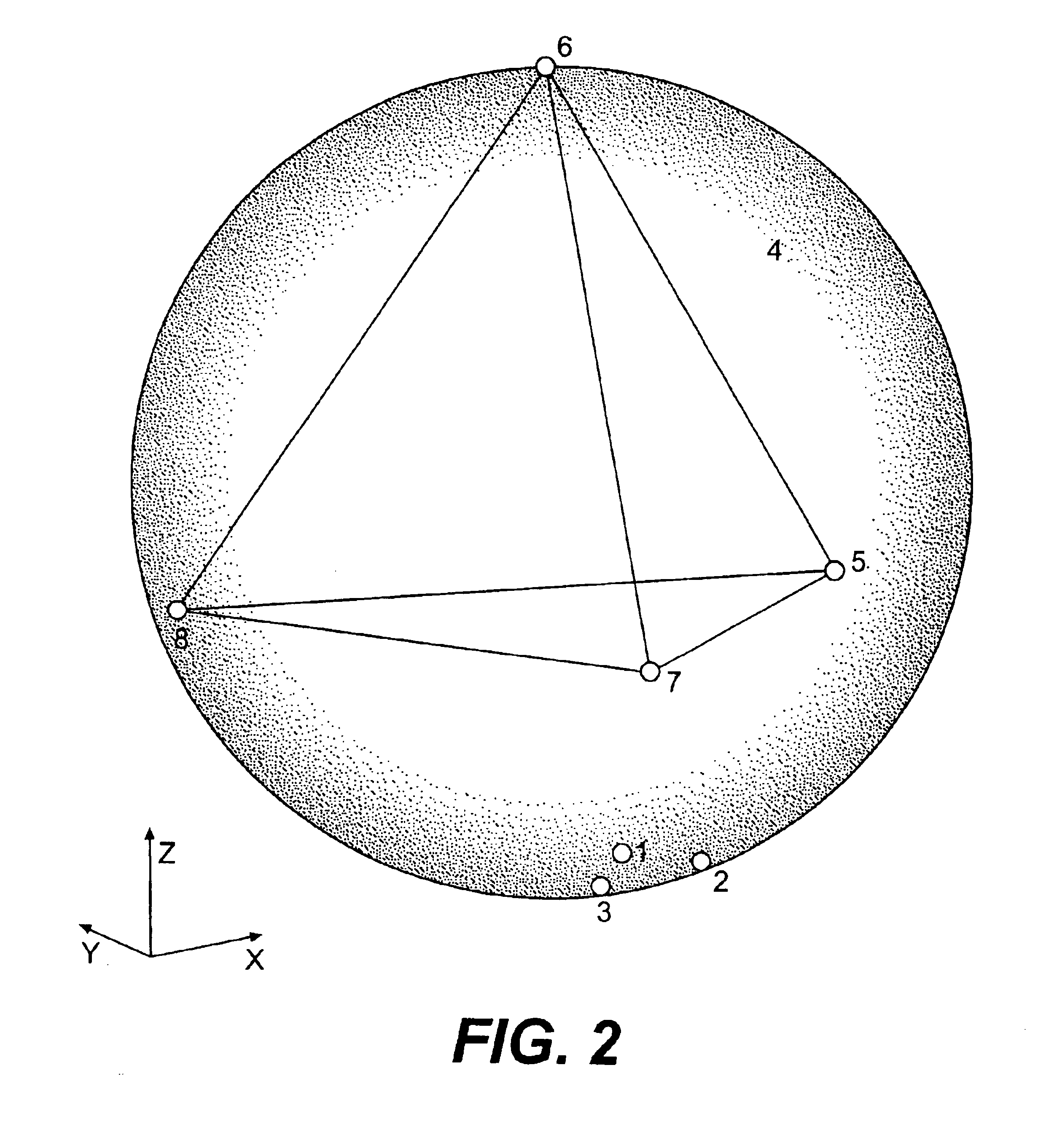
[0065]The first example, shown in FIG. 2, utilizes only four points to provide a simplified illustration of how the present invention can be used to arrange dimples on a spherical surface. In this example, the defined surface corresponds to a unit sphere. The four points are randomly placed in any location on the surface of the sphere, as represented by numbers 1-4, and assigned identical charge values. Using a computer, the potential, gradient, minimum distance between any two points and average distance between all of them is calculated. The dimples are then repositioned according to a gradient based solution method and reevaluated. As shown in FIG. 1, and as further illustrated in Table 1 below, this process is repeated in this example until the gradient is approximately zero.

[0066]

TABLE 1IterationPotentialsMinimumAtAverageNo.PEGradientDistanceVerticesDistance18.20512.2300.50390, 11.1331264.4221.5201.0760, 11.4273514.0690.9251.24690, 11.5165763.9140.6631.34120, 11.56261013.8290.5...

example 2

[0068]The second example uses the methods described herein to arrange 24 dimples on a golf ball. In this example, the initial dimple locations 1-24 once again are randomly arranged on the surface of the golf ball. The initial configuration of the dimple locations 1-24 is shown in FIG. 4. Charge values are assigned, and the potential, gradient, and minimum and average distances are again calculated. The process is repeated as described above for Example 1 until the dimple locations are optimized. Although the optimized dimples are not numbered, FIG. 4 shows the optimized positioning of the dimples, which coincide with vertices of an Archimedean shape.

[0069]As shown in FIG. 5, the rate of convergence again is was approximately linear. Table 2, below, provides illustrative data showing the calculations performed in this example. In this example, the process was stopped after 2160 iterations when the gradient reached an acceptable tolerance. Although not utilized in this Example, additi...

example 3

[0072]FIGS. 6 and 7 show the initial and final dimple configurations for a 392-icosahedron dimple layout with two dimple diameters. It is provided that 392 circular dimples are distributed on the entire spherical surface of a golf ball. Using a computer, an initial distribution of dimples is set on a hemispherical surface of a golf ball model. The initial distribution shown in FIG. 6 is based on a conventional icosahedral arrangement of dimples. In this example, there are two dimple sizes on the ball. The first set of dimples have a diameter of about 0.139 inches, while the second set of dimples are about 0.148 inches in diameter. Each hemisphere of the ball has 196 dimples.

[0073]As seen in FIG. 6, the initial dimple pattern shows large polar spacing and tighter packing toward the equator of the ball, but maintains a sufficient setback from the equator of the ball. In this example, the defined space for redistributing the dimples is approximately a hemisphere with a constraint that ...


PUM


Abstract

A golf ball having a plurality of dimples on its surface, the dimples as a whole are distributed on at least a portion of the golf ball using principles of electromagnetic theory. The dimples placed on the golf ball surface are assigned charge values that are used to determine the electric potential. A solution method is then applied to minimize the potential by rearrangement of the dimple positions.

Description

CROSS-REFERENCE TO RELATED APPLICATIONS[0001]This application is a continuation of U.S. patent application Ser. No. 10 / 237,680, filed Sep. 10, 2000 now U.S. Pat. No. 6,702,696, now allowed, the disclosure of which is incorporated by reference herein in its entirety.FIELD OF THE INVENTION[0002]This invention relates to a method of distributing dimples on a golf ball utilizing principles of electromagnetic field theory.BACKGROUND OF THE INVENTION[0003]One of the most fundamental equations in engineering mathematics is Laplace's Equation. A number of physical phenomena are described by this partial differential equation including steady-state heat conduction, incompressible fluid flow, elastostatics, as well as gravitational and electromagnetic fields. The theory of solutions of this equation is called potential theory.[0004]One example of potential theory is electromagnetic field theory, which can be used to distribute objects on a spherical surface. Electromagnetic field theory has b...

Claims


Application Information

Patent Timeline
Patent Type & Authority Patents(United States)
IPC IPC(8): A63B37/00
CPCA63B37/0004A63B37/0006A63B37/0021A63B37/0018A63B37/0009A63B37/00065
Inventor NARDACCI, NICHOLAS M.
Owner ACUSHNET CO
Why Eureka
Try Eureka