High flow, one piece automotive air filter

a technology of automotive air filter and one piece, applied in the direction of combustion-air/fuel-air treatment, filtration separation, separation process, etc., can solve the problems of reducing engine efficiency, horsepower, torque, fuel economy, and other performance parameters, and affecting the efficiency of the particular combustion system. , to achieve the effect of increasing particle trapping

Inactive Publication Date: 2005-04-26
ADVANCED FLOW ENG
View PDF13 Cites 23 Cited by
  • Summary
  • Abstract
  • Description
  • Claims
  • Application Information

AI Technical Summary

Problems solved by technology

Particulate material can cause substantial damage to the internal components of the particular combustion system if taken into the engine.
The features and filter design choices that lead to improvements in one of these parameters can lead to losses in the other performance parameters.
This tends to decrease engine efficiency, horsepower, torque, and fuel economy.
However, in approaching high volumetric flow applications, existing filters that provide a significantly improved filter flow rate may foster air turbulence at the filter intake, an undesirable quality which ultimately impairs air flow.
Because air eddies can cause the influent air to bypass regions of the filter media near these abrupt transitions, the effective area available for filtration is reduced.
Filters using multiple pieces also may be prone to allowing nuts, caps and attachment devices to fall into the engine air intake during maintenance.
Such an event would be highly undesirable, for example, during a high-performance automotive race.
The deleterious effects of certain harsh operating environments, such as construction sites, long haul operations and off-road, recreational, and sports applications, can lead to degraded efficiency or unacceptably short lifetimes in these air filters, especially under high airflow conditions.
In some cases, existing high-efficiency air filters may not be capable of providing the desired volumetric flow rate under extreme conditions.
Also, an efficacious amount of oil can be used to wet the cotton mesh layers, thereby increasing particle trapping by cotton mesh filter media.

Method used


Image

  • High flow, one piece automotive air filter
  • High flow, one piece automotive air filter
  • High flow, one piece automotive air filter

Examples


Embodiment Construction

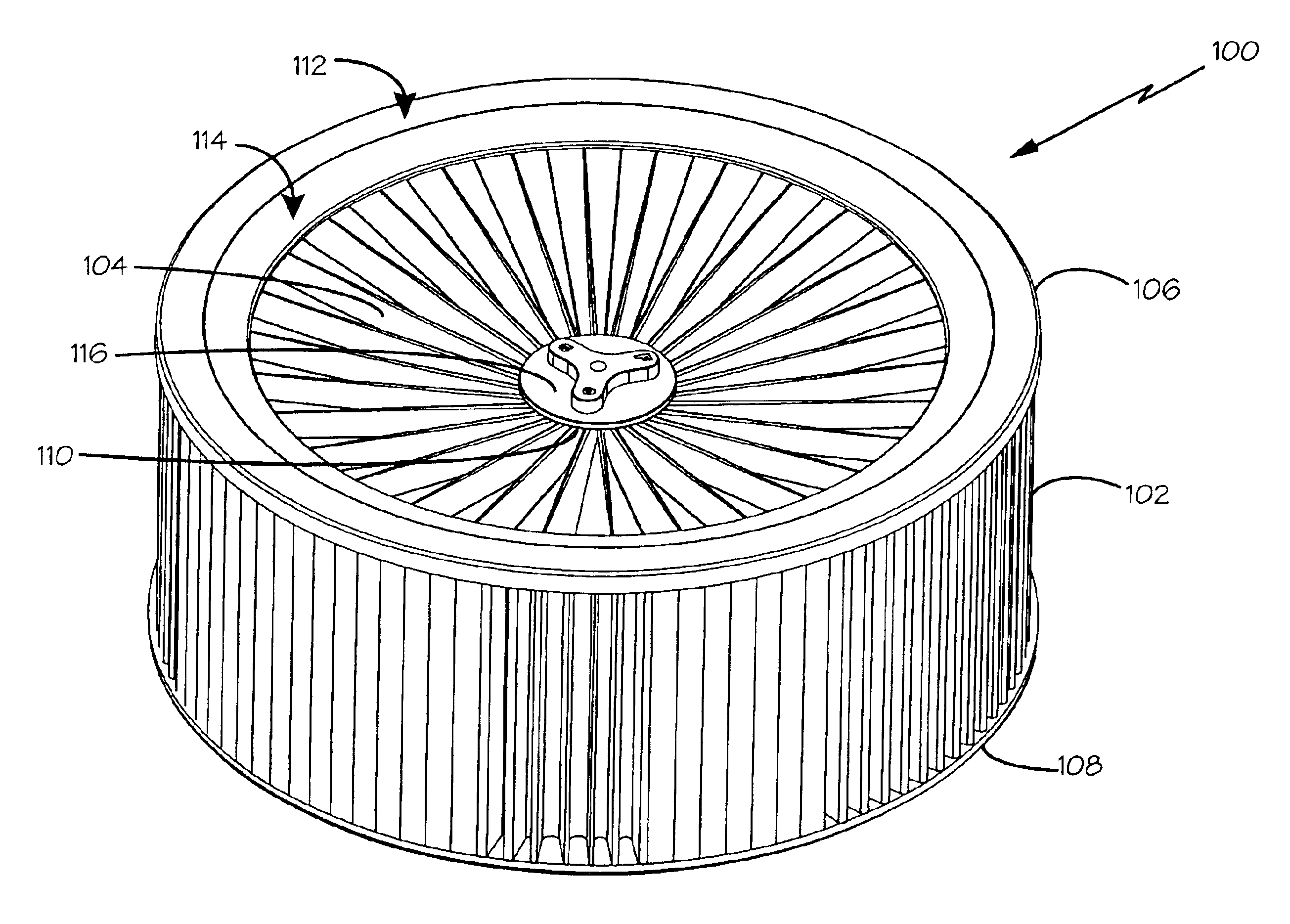
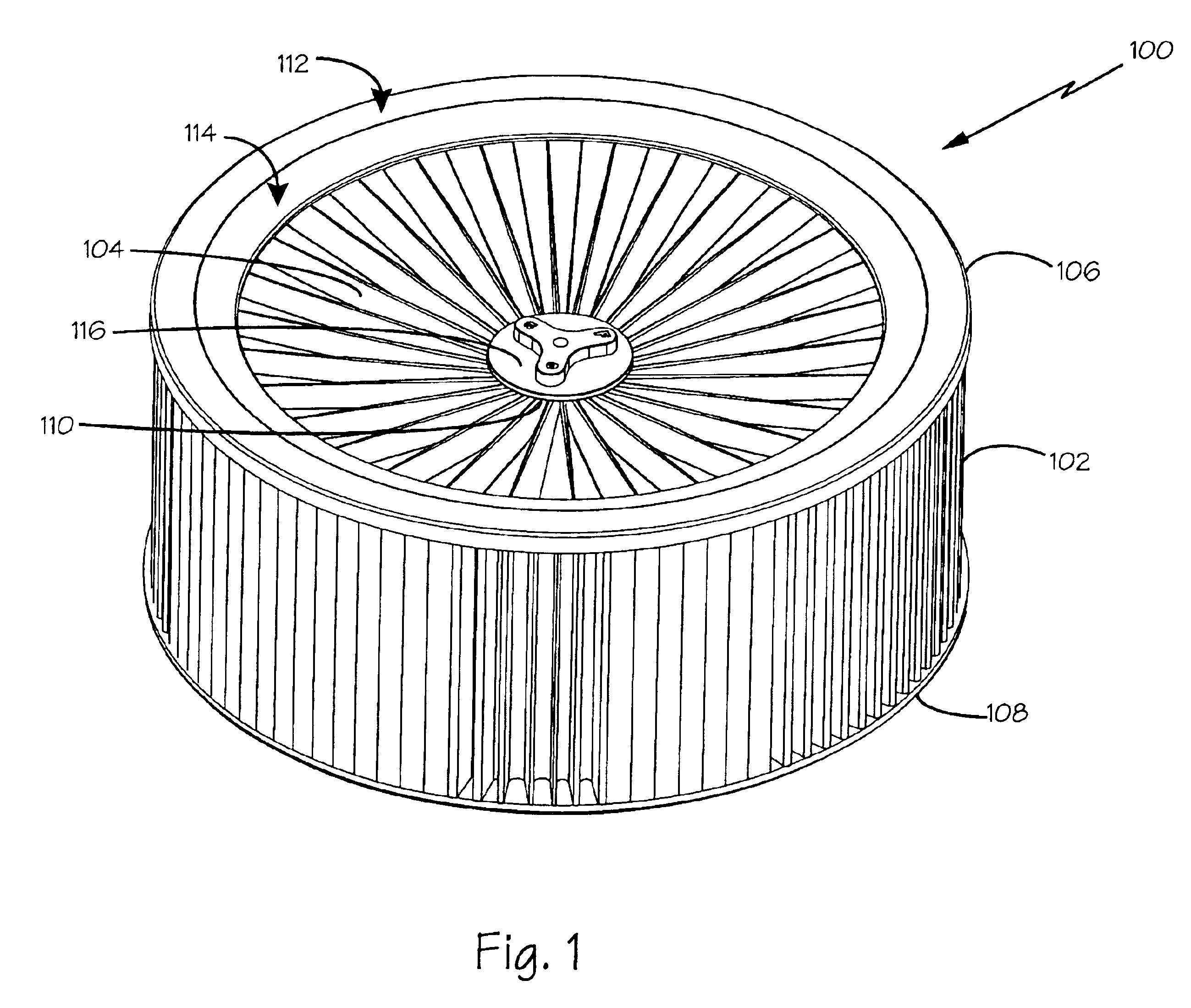
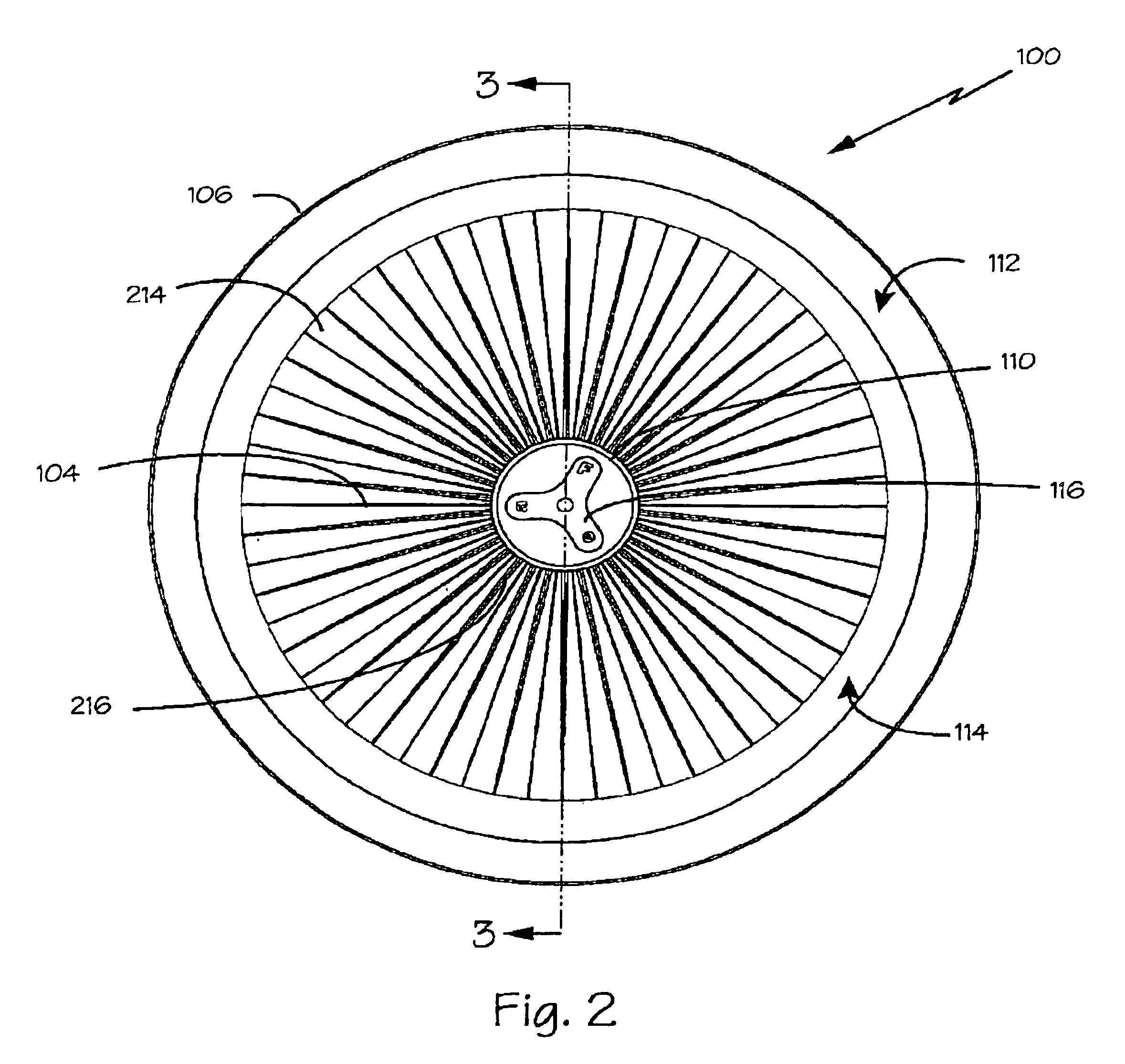
[0022]In FIG. 1, air filter 100 is shown to have sidewall section 102, cap section 104, and crown 106. Sidewall section 102 and cap section 104 comprise filter media. Filter 100 also can include either seat 108 and flange 110, or both. Crown 106, formed of land 112 and bevel 114, sealably conjoins, or unifies, sidewall section 102 and cap section 104 into one-piece filter 100. Conveniently, the arrangement of filter 100 causes the entering air to be filtered both by sidewall section 102 and by cap section 104.

[0023]Land 112 is a generally flat portion of crown 106, which desirably is positioned on the upper surface of sidewall section 102. Land 112 can be slightly contoured where it meets bevel 114, or the tilted crown section integral with land 106, and interposed between land 106 and cap section 104.

[0024]Tensioner 116 is used to impose a force upon flange 110 (shown in detail in FIG. 3) and, in turn upon cap section 104 to create a seal between flange 110 and tensioner 116. A por...


PUM

PropertyMeasurementUnit
thickaaaaaaaaaa
diameteraaaaaaaaaa
oleophilicaaaaaaaaaa

Abstract

Air filter with a sidewall and inverted cone cap sections; a beveled crown unifying the sidewall with the cap to form a one-piece filter; a seat on the bottom of the wall section with seals for contact with a support; and a flange affixed to the cap to adjust contact with a support surface. The filter media includes four-layer oleophilic cotton mesh layers supported between two structural mesh layers, with an efficacious amount of oil to increase particle trapping.

Description

FIELD OF THE INVENTIONS[0001]The inventions described below relate the field of automotive air filters and air cleaners for engine air intake systems.BACKGROUND OF THE INVENTIONS[0002]Most people are familiar with air filters used in their cars. These filters are essential to proper operation of the engine, and help extend the life of the engine and its components. The air available to the typical automotive or industrial combustion engine always includes some dirt and debris, or particulate material. Particulate material can cause substantial damage to the internal components of the particular combustion system if taken into the engine.[0003]The function of the air intake filter is to remove the particulate matter from the intake air, so that clean air is provided to the engine. The intake air stream flows from the influent, or “dirty,” side of the filter to the effluent, or “clean,” side of the filter, with the air filter extracting the unwanted particles via one or more filter me...

Claims


Application Information

Patent Timeline
Patent Type & Authority Patents(United States)
IPC IPC(8): B01D46/52B01D39/08B01D39/16B01D46/00B01D46/24
CPCB01D39/083B01D39/1615B01D46/0005B01D46/2414B01D46/523B01D2275/10B01D2239/065B01D2239/0654B01D2239/069B01D2239/1291B01D2239/0627
Inventor NIAKAN, SHAHRIAR NICKMIYAGISHIMA, STUART T.BEAU, CHRISTOPHER C.MORALES, OSCAR
Owner ADVANCED FLOW ENG
Why Eureka
Try Eureka