

Polycarbonate and resin composition
a technology of polycarbonate and resin, applied in the field of polycarbonate, can solve the problems of affecting the mechanical and thermal properties of polycarbonate, and achieve the effect of excellent non-combustibility and hydrolytic resistan
- Summary
- Abstract
- Description
- Claims
- Application Information
AI Technical Summary
Benefits of technology
Problems solved by technology
Method used
Image

Examples
example 1
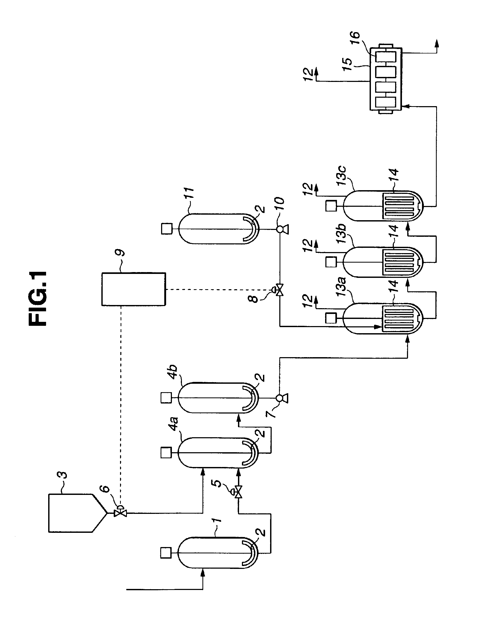
[0104]An example of the polycarbonate producing method according to the present invention is explained with reference to FIG. 1. FIG. 1 is a flow sheet of the production process in an embodiment of the present invention, in which reference numeral 1 indicates a diphenyl carbonate (DPC) tank, 2 agitators, 3 a bisphenol A (BPA) hopper, 4a and 4b material mixing tanks, 5 a DPC flow rate control valve, 6 a BPA flow rate control valve, 7 a pump, 8 a catalyst flow rate control valve, 9 a program control unit, 10 a pump, 11 a catalyst tank, 12 by-product discharge pipes, 13a, 13b and 13c vertical polymerizers, 14 Max Blend agitator, 15 a horizontal polymerizer, and 16 gate paddle agitators.
[0105]A melt of diphenyl carbonate prepared at 120° C. in a nitrogen gas atmosphere and a bisphenol A powder weighed in a nitrogen gas atmosphere were metered by a micro-motion type flowmeter and a loss-in-weight type weight feeder so that they would be fed at the rates of 208.9 mol / h from the DPC tank (...
example 2
[0115]The same procedure as defined in Example 1 was conducted except that the setting molar ratio of the materials was changed to 1.040 and the catalyst flow rate to 1.60 mL / h (setting amount of catalyst: 0.5 μmol for one mole of bisphenol A), that the temperature of the fourth polymerizer was set at 280° C., and that butyl p-toluenesulfonate was added in an amount of 4.0 ppm (4.4 times the neutralized amount of catalyst) based on the weight of the polycarbonate. The viscosity-average molecular weight (Mv) and the terminal OH group content of the obtained polycarbonate were 21,500 and 500 ppm, respectively.
[0116]The time in which the actual amount of catalyst remained within the range of the setting amount of catalyst of ±0.06 μmol and ±0.1 μmol for one mole of the aromatic dihydroxyl compound was calculated from the continuous metering data of catalyst flow rate control valve. The percentages of the time satisfying the above specified ranges were 96.7% and 99.1%, respectively, of ...
example 3
[0118]The same procedure as defined in Example 1 was carried out except that the setting molar ratio of the materials was changed to 1.040 and the catalyst flow rate to 1.1 mL / h (setting amount of catalyst: 0.35 μmol for one mole of bisphenol A), that the temperature of the fourth polymerizer was set at 280° C., the pressure at 2.66×10 Pa and the stirring rate at 10 rpm, and that butyl p-toluenesulfonate was added in an amount of 2.8 ppm (4.5 times the neutralized amount of catalyst) based on the weight of the polycarbonate. The viscosity-average molecular weight (Mv) and the terminal OH group content of the obtained polycarbonate were 21,800 and 500 ppm, respectively.
[0119]The time in which the actual amount of catalyst remained within the range of the setting amount of catalyst of ±0.06 μmol and ±0.1 μmol for one mole of the aromatic dihydroxyl compound was calculated from the continuous metering data of catalyst flow rate control valve. The percentages of the time satisfying the ...
PUM
| Property | Measurement | Unit |
|---|---|---|
| Temperature | aaaaa | aaaaa |
| Fraction | aaaaa | aaaaa |
| Angular velocity | aaaaa | aaaaa |
Abstract
Description
Claims
Application Information