Method, system, and apparatus for management of reaction loads in a lithography system

a technology of lithography system and reaction load, applied in the field of lithography system, can solve the problems of reducing the operational precision of the lithography system, reaction load or reaction movement, etc., and achieve the effects of preventing vibration, preventing vibration, and compromising the isolation of the structur

Inactive Publication Date: 2005-04-26
ASML HLDG NV
View PDF16 Cites 10 Cited by
  • Summary
  • Abstract
  • Description
  • Claims
  • Application Information

AI Technical Summary

Benefits of technology

[0010]The combination of the flexure rod and parallel flexure mechanism provides a high degree of compliance in all six degrees of freedom, thus preventing vibration from being coupled from the non-isolated structure to the isolated structure. The isolated structure remains free to move with respect to non-isolated structure.
[0011]The passive flexured mechanism of the present invention directly transfers motion related loads from the second element of the linear motor to the non-isolated support structure

Problems solved by technology

Acceleration of system components during their movement can cause a reaction load or reaction movement in components of the system being moved against, and in the support structure.
Reaction movem

Method used


Image

  • Method, system, and apparatus for management of reaction loads in a lithography system
  • Method, system, and apparatus for management of reaction loads in a lithography system
  • Method, system, and apparatus for management of reaction loads in a lithography system

Examples


Embodiment Construction

1. Overview

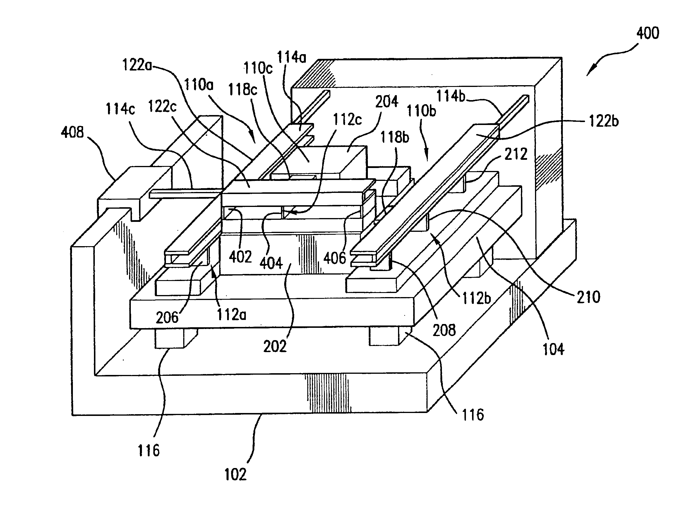
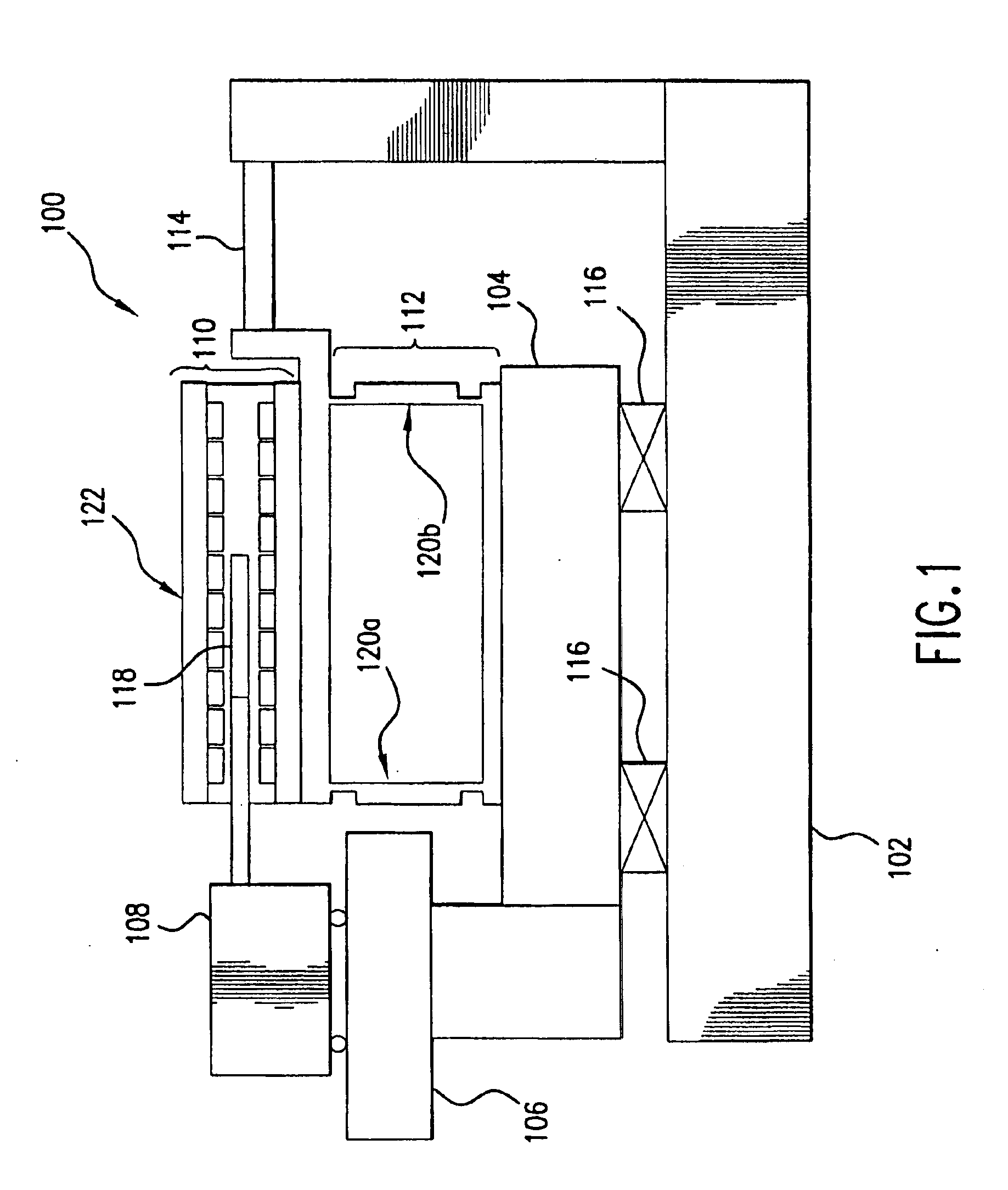
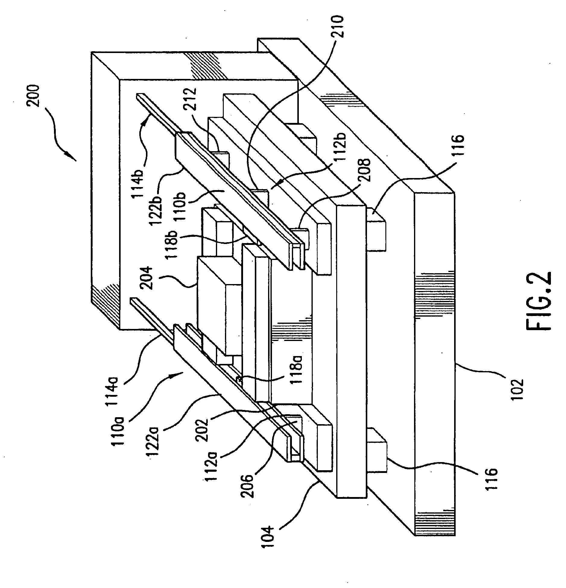
[0033]The present invention is directed to a method, system, and apparatus for reducing motion loads, and hence reducing relative motion between, and the shaking of portions of a lithography tool. According to the present invention, a linear motor is used to move a lithography system stage that is mounted on an isolated structure. The linear motor includes a first linear motor element and a second linear motor element, such as a coil and a stator. The isolated structure is supported on a non-isolated support structure. The present invention uses a passive flexured mechanism to directly transfer motion related loads from the second element of the linear motor to the non-isolated support structure. This transfer is accomplished without dissipating substantial power, or compromising the isolation of the structure on which the stage is mounted. By reducing the motion loads, and hence reducing the shaking of lithography system components, semiconductor wafers may be more preci...


PUM


Abstract

A method, system, and apparatus for management of reaction loads in a lithography system is described. An isolated structure is supported by a non-isolated structure. The isolated structure supports a moveable stage. A linear motor includes a first linear motor element and a second linear motor element. The first linear motor element is coupled to the moveable stage. A plurality of parallel flexure plates mount the second linear motor element on the isolated structure. A flexure rod is coupled between the non-isolated structure and the second linear motor element.

Description

[0001]This is a continuation application of U.S. application Ser. No. 10 / 095,070, filed Mar. 12, 2002, now U.S. Pat. No. 6,784,978 which is herein incorporated by reference in its entirety.BACKGROUND OF THE INVENTION[0002]1. Field of the Invention[0003]The invention relates generally to the field of lithography systems and, more particularly, to management of reaction loads in a lithography tool.[0004]2. Background Art[0005]In the fabrication of integrated circuits, lithographic and projection printing techniques are used. Lithography is a process used to create features on the surface of substrates. Such substrates can include those used in the manufacture of flat panel displays, circuit boards, various integrated circuits, and the like. A frequently used substrate for such applications is a semiconductor wafer. During lithography, exposure optics located within a lithography apparatus project an image in a reticle onto the surface of a semiconductor wafer. The wafer is disposed on...

Claims


Application Information

Patent Timeline
IPC IPC(8): G03F7/20H01L21/027
CPCG03F7/70758G03F7/709G03F7/70833G03F7/20
Inventor GALBURT, DANIEL N.
Owner ASML HLDG NV
Why Eureka
Try Eureka