
Fluorescent X-ray analysis apparatus

Inactive Publication Date: 2005-04-26
MITSUBISHI ELECTRIC CORP
View PDF5 Cites 16 Cited by
  • Summary
  • Abstract
  • Description
  • Claims
  • Application Information

AI Technical Summary

Benefits of technology

[0007]A fluorescent X-ray analysis apparatus according to this invention enables change of the focal position of an irradiation X-ray (primary X-ray) in accordance with a change of the surface position of an irradiation object in order to monitor the concentration of a metal element in various liquids, the composition of a thin film, the thickness of the film or the like in an in-line process. This secures stable irradiation intensity (intensity per unit area) of the primary X-ray on the surface of the irradiation object and also secures stable intensity of a secondary X-ray that is necessary for in-line process monitoring of the composition of the surface of the irradiation object, the thickness of the film or the like.
[0008]Since the fluorescent X-ray analysis apparatus according to this invention includes: an X-ray generation source for radiating a primary X-ray; plural spectroscopic elements circularly arranged so that their inner surfaces constitute a circle centering on an optical axis of the primary X-ray and adapted for monochromatizing and condensing the primary X-ray on a surface of an irradiation object; a spectroscopic element position adjusting means for adjusting the positions of the plural spectroscopic elements; a secondary X-ray detector for detecting a secondary X-ray radiated from the surface of the irradiation object upon irradiation with the monochromatized primary X-ray; a secondary X-ray detector position adjusting means for adjusting the position of the secondary X-ray detector; an irradiation object surface position detecting means for detecting the position of the surface of the irradiation object; and a control means for adjusting the positions of the plural spectroscopic elements by the spectroscopic element position adjusting means so as to condense the monochromatized primary X-ray on the surface of the irradiation object, on the basis of information of the position of the surface of the irradiation object detected by the irradiation object surface position detecting means, the primary X-ray having necessary intensity for analysis can be accurately irradiated onto the surface position of the irradiation object even when the surface position of the irradiation object changes. Thus, a fluorescent X-ray analysis apparatus that enables monitoring an element of various liquids with changing surface positions, composition of a thin film, the thickness of the film and the like in an in-line process is realized.

Problems solved by technology

During an actual manufacturing process, it is almost impossible to install an irradiation object constantly at a predetermined position and the surface height of the irradiation object often changes.
It has no detecting means for detecting the changing surface position of the irradiation object, either.
Moreover, the conventional portable fluorescent X-ray analysis apparatus basically requires that a sample has a smooth surface, and miniaturization of the apparatus limits the quantity of X-ray irradiation.
Therefore, a detector for a secondary X-ray must be arranged very closely to the irradiation object, and even when a moving means is provided, the apparatus cannot be applied to in-line monitoring.

Method used


Image

  • Fluorescent X-ray analysis apparatus
  • Fluorescent X-ray analysis apparatus
  • Fluorescent X-ray analysis apparatus

Examples


embodiment 1

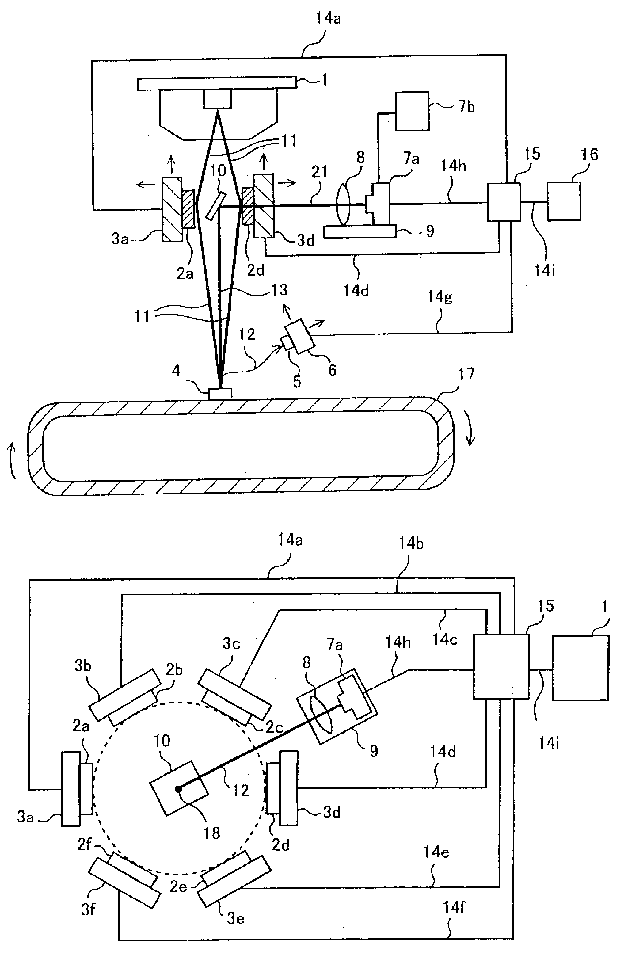
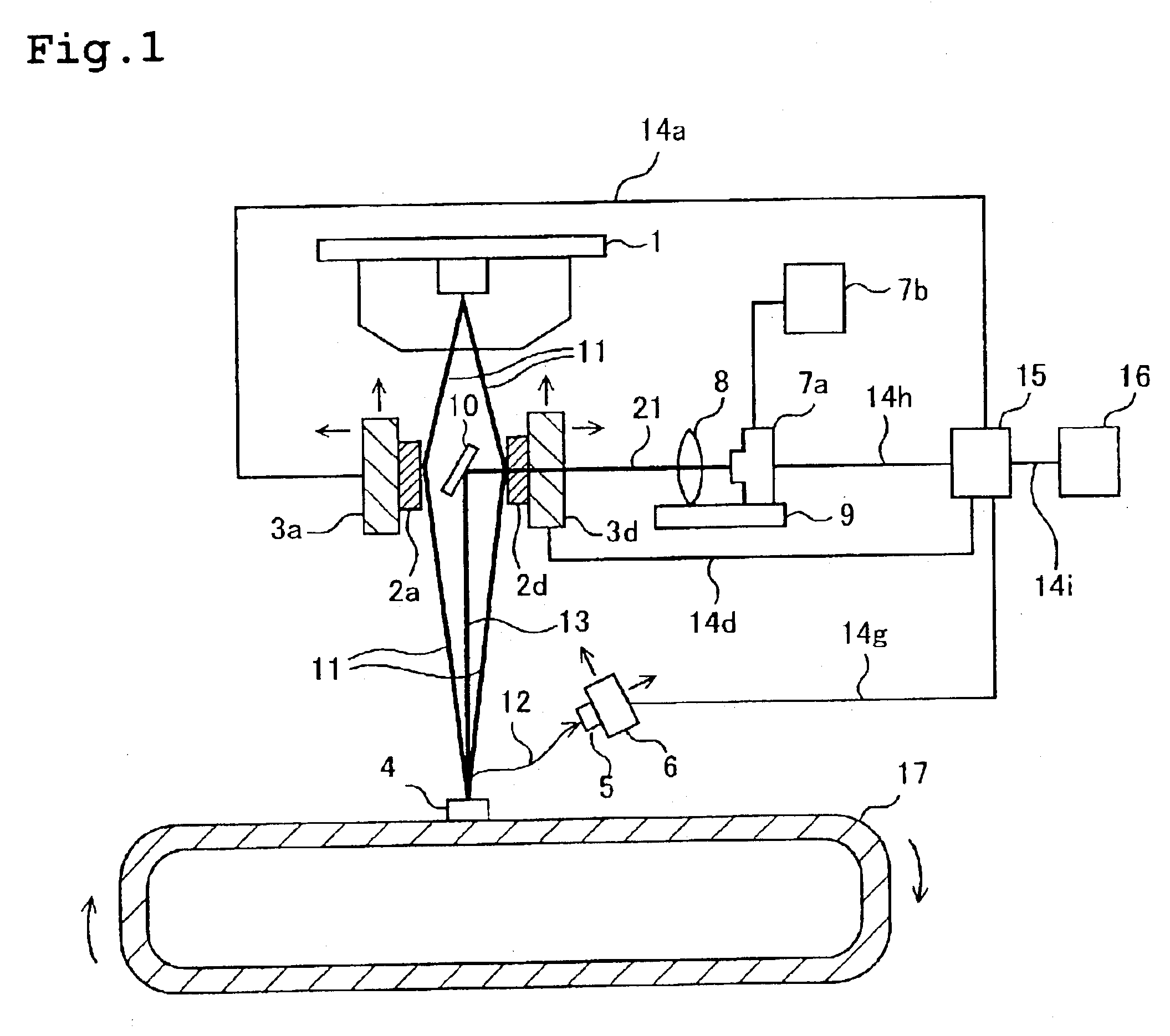
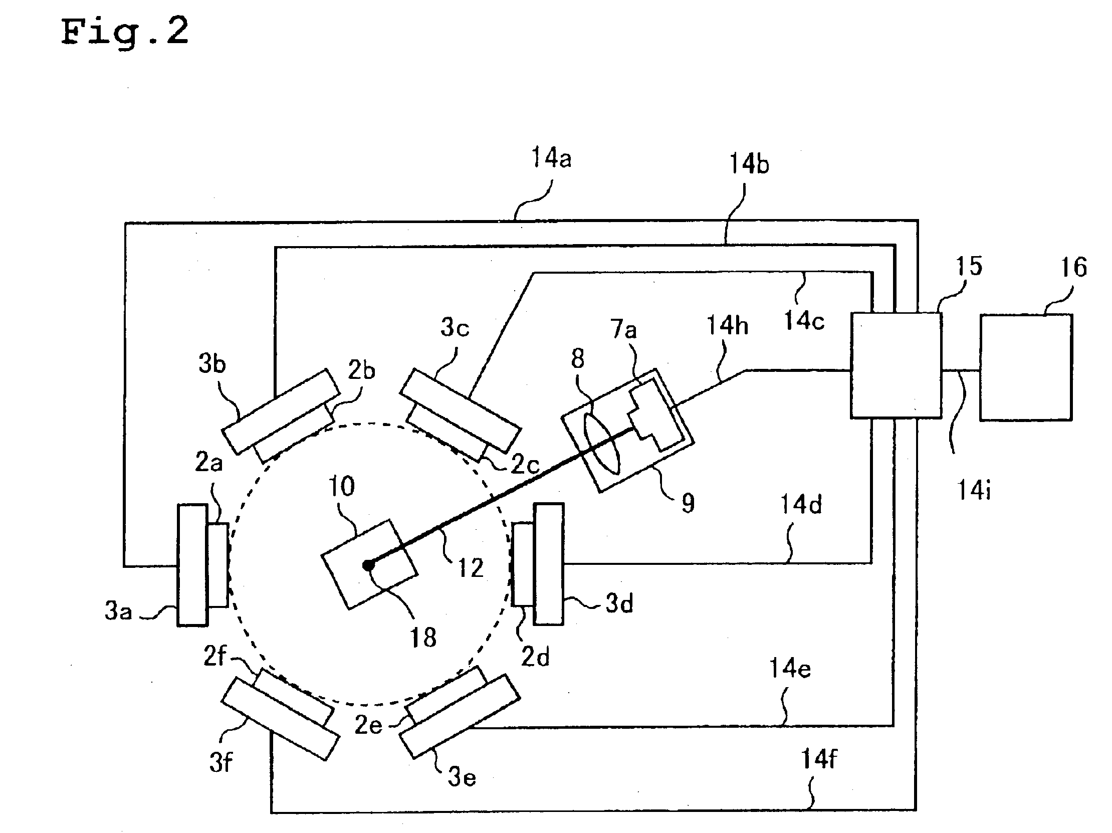
[0013]FIG. 1 is an explanatory view showing a cross-sectional structure of a fluorescent X-ray analysis apparatus according to this invention. FIG. 2 is an explanatory view showing a structure of the fluorescent X-ray analysis apparatus of FIG. 1 as viewed from its top. The operation of the apparatus will now be described with reference to the drawings.

[0014]A primary X-ray 11 radiated from an X-ray tube (X-ray generation source) 1 is spectrally divided by spectroscopic elements 2a to 2f and the primary X-ray 11 is monochromatized. (In FIG. 1, only 2a and 2b are shown.) Monochromatization of the primary X-ray 11 is for the purpose of improving the analytic sensitivity of the fluorescent X-ray analysis apparatus. Specifically, the primary X-ray 11 radiated from the X-ray tube 1 usually has a certain width of wavelengths. However, if the primary X-ray 11 has a width of wavelengths, it becomes a noise source in generation and detection of a secondary X-ray, which will be described late...

embodiment 2

[0033]FIG. 3 is an explanatory view showing a cross-sectional structure of a fluorescent X-ray analysis apparatus according to this invention. In this embodiment, instead of the detection device for the surface position of a sample using the CCD camera in the apparatus described in Embodiment 1, a laser beam irradiating unit 19 and a laser beam detecting unit 20 are provided to measure the distance between an X-ray tube 1 and the surface of a sample 4 using a laser beam 22, thereby detecting the surface position of the sample and adjusting the positions of spectroscopic elements 2a to 2f. The laser beam irradiating unit 19, and the laser beam detecting unit 20 are connected with a control unit 15 by connection lines 14h and 14h′ and the measured distance between the X-ray tube 1 and the surface of the sample 4 is communicated to the control unit 15. With this structure, though the sample surface cannot be visually monitored, a commercially available laser-based length measuring mach...

embodiment 3

[0037]FIGS. 4A to 4C are explanatory views showing a structure of a fluorescent X-ray analysis apparatus according to this invention. In this embodiment, curved spectroscopic elements are used instead of the parallel plate-like spectroscopic elements of the apparatus described in Embodiment 1. Specifically, as shown in FIG. 4A, spectroscopic elements 2a to 2f are connected with spectroscopic element moving devices 3a to 3f via spectroscopic element curved shape adjusting means 23a to 23f including plural actuators and therefore can be adjusted to have a predetermined curved shape in accordance with a position change. FIG. 4A typically shows only the spectroscopic element 2a, the actuator 23a and the spectroscopic element moving device 3a. The actuators 23a to 23f are connected with a controller 5 by connection lines, not shown, and when the spectroscopic elements 2a to 2f move, the surfaces of the spectroscopic elements 2a to 2f are adjusted to have the following curved shape.

[0038]...


PUM


Abstract

A fluorescent X-ray analysis apparatus includes: an X-ray generation source for radiating a beam of primary X-rays; spectroscopic elements circularly arranged so that their inner surfaces describe a circle centered on an optical axis of the beam of primary X-rays for monochromatizing the beam of primary X-rays and condensing the beam on a surface of an irradiation object; a spectroscopic element position adjuster for adjusting the positions of the spectroscopic elements; secondary X-rays detector for detecting secondary X-rays radiated from the surface of the irradiation object irradiated with the monochromatized beam of primary X-rays; a secondary X-ray detector position adjuster adjusting the position of the secondary X-ray detector; an irradiation object surface position detector detecting the position of the surface of the irradiation object; and a controller adjusting the positions of the spectroscopic elements through the spectroscopic element position adjuster to condense the monochromatized beam of primary X-rays on the surface of the irradiation object, on the basis of the position of the surface of the irradiation object detected by the irradiation object surface position detector.

Description

BACKGROUND OF THE INVENTION[0001]1. Field of the Invention[0002]This invention relates to a fluorescent X-ray analysis apparatus, and particularly to a fluorescent X-ray analysis apparatus for monitoring the concentration of an element in a liquid, and the composition or thickness of a thin film during a manufacturing process.[0003]2. Description of the Related Art[0004]A fluorescent X-ray analysis apparatus is used for measuring the composition of various materials and the thickness of a film during an electronic device manufacturing process or the like. An ordinary fluorescent X-ray analysis apparatus has an analysis chamber, which increases the scale of the apparatus, and conventionally the apparatus is only used in sampling inspection for evaluation of the samples. Recently, however, in order to improve the yield and quality of products in manufacture of semiconductors, it has become increasingly necessary to analyze the composition of various materials and the thickness of a fi...

Claims


Application Information

Patent Timeline
IPC IPC(8): G01N23/22G01N23/223G21K1/00G21K1/06
CPCG01N23/223G21K1/06G01N2223/076
Inventor UEHARA, YASUSHISHIBANO, TERUO
Owner MITSUBISHI ELECTRIC CORP
Learn More