Communication device using bone conduction

a communication device and bone technology, applied in the field of communication devices, can solve the problems of loss of available efficiency, difficulty in matching to an acoustic radiator, especially to the air, etc., and achieve the effects of low cost, low weight and high conversion efficiency

Inactive Publication Date: 2005-04-26
GOOGLE LLC
View PDF31 Cites 98 Cited by
  • Summary
  • Abstract
  • Description
  • Claims
  • Application Information

AI Technical Summary

Benefits of technology

[0019]The advantages are that the transducer may be manufactured at very low cost and thus the communication devices may be disposable. Furthermore, the transducers may be low weight and small, e.g. less than 3 grams, but still having a high conversion efficiency. Thus they may be used in devices, e.g. in mobile telephones, where previous bone conduction arrangements are unsuitable, because of their weight and bulkiness. The communication devices using intendedly modal transducers for bone conduction may have also reduced acoustic feedback.
[0020]The transducer may comprise a plurality of resonant elements each having a distribution of modes, the modes of the resonant elements being arranged to interleave in the operative frequency range and thus enhance the distribution of modes in the transducer as a whole device. The resonant elements may have different fundamental frequencies and thus, the parameters, e.g. loading, geometry or bending stiffness of the resonant elements may be different.

Problems solved by technology

There are several problems with piezoelectric transducers, for example, they are inherently very stiff, for example comparable to brass foil, and are thus difficult to match to an acoustic radiator, especially to the air.
This leads to a loss in available efficiency.

Method used


Image

  • Communication device using bone conduction
  • Communication device using bone conduction
  • Communication device using bone conduction

Examples


Embodiment Construction

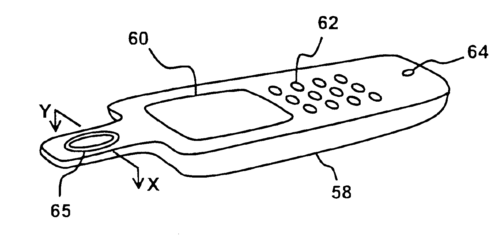
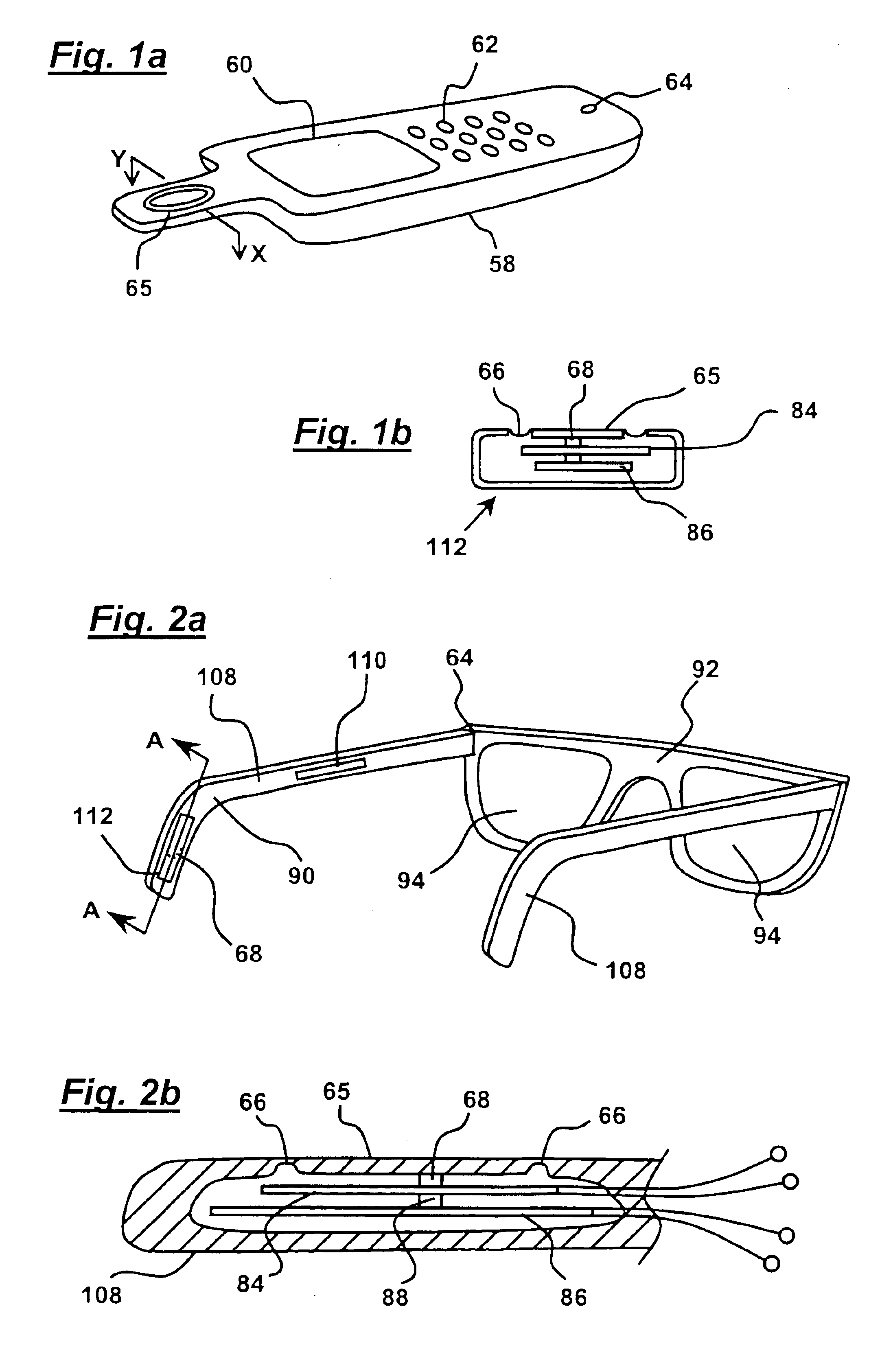
[0048]FIGS. 1A and 1B show a mobile handset (58), e.g. for use as a mobile or cellular phone, which comprises a microphone (64), buttons (62) forming a keypad, and a screen (60). The microphone is mounted in one end of the handset and the opposed end of the handset (58) is formed with an extension. An intendedly modal transducer or distributed mode transducer as hereinbefore described and as described in WO01 / 54450 and corresponding U.S. application Ser. No. 09 / 768,002, is mounted in the extension so as to drive a conduction interface (65).

[0049]As shown more clearly in FIG. 1B, the distributed mode transducer comprises upper and lower bimorph beams (84) and (86), the upper beam (84) being connected to the conduction interface (65) via a short stub (68) which extends across the width of the beams. The stub may be 1-2 mm wide and high and may be made from hard plastics and / or metal with suitable insulating layers to prevent electrical short circuits.

[0050]The beams are of unequal len...


PUM


Abstract

A communication device comprising a microphone, a conduction interface and an electromechanical force transducer mounted to the conduction interface to drive the interface to conduct sound to a user by bone conduction, characterised in that the transducer has an intended operative frequency range and comprises a resonant element having a frequency distribution of modes in the operative frequency range and coupling means for mounting the transducer to the interface.

Description

[0001]This application claims the benefit of provisional application No. 60 / 303,802, filed Jul. 10, 2001 (incorporated by reference in its entirety) and is a continuation-in-part application of U.S. application Ser. No. 09 / 768,002, filed Jan. 24, 2001, which claims the benefit of U.S. provisional Nos. 60 / 178,315, filed Jan. 27, 2000; 60 / 205,465, filed May 19, 2000 and 60 / 218,062, filed Jul. 13, 2000.TECHNICAL FIELD[0002]The invention relates to communication devices such as telephones, headsets or hearing aids which use bone conduction to transmit sound to a user.BACKGROUND ART[0003]Bone conduction is an established technique which enables deaf people to communicate. Typical examples comprise a transducer which is mounted adjacent a user's ear so as to transmit sound to a user via conduction through the mastoid bone. However, known devices suffer from drawbacks such as excess pressure on the skull and the necessity of a heavy transducer means that their use is limited. For example, ...

Claims


Application Information

Patent Timeline
Patent Type & Authority Patents(United States)
IPC IPC(8): H04M1/04H04M1/05H04R7/04H04R1/00H04R7/00H04R1/02H04R1/46H04R17/00
CPCH04M1/05H04R1/028H04R1/46H04R7/045H04R2499/13H04R17/00H04R2460/13
Inventor BANK, GRAHAM
Owner GOOGLE LLC
Why Eureka
Try Eureka