
Personal communication device connectivity arrangement

a technology of personal communication device and connectivity arrangement, which is applied in the field of medical devices, can solve problems such as extraneous radio frequency emission, and achieve the effect of restricting propagation

Inactive Publication Date: 2005-04-26
AMBIT ENERGY +1
View PDF29 Cites 41 Cited by
  • Summary
  • Abstract
  • Description
  • Claims
  • Application Information

AI Technical Summary

Benefits of technology

[0010]The docking system may comprise a “zone” or “focal area” as a generally rectilinear area / volume on / in a desk or work surface on / in which the electronic communication device may be placed, such a surface or space being possible on a desk, or in a plane. That focal area may also, in a further embodiment, be comprised of one or more rooms in a building, such focal area having a pick-up probe thereat, in conjunction with a shield placed on / in the desk, room, vehicle or building to prevent the radiation from that communication device from traveling in any undesired directions within the desk, room, vehicle or building.
[0011]The focal area may be defined by a metal walled structure within or on which a broadband probe is arranged. The metal walled structure acts as a shield to minimize radiation from the communication device from passing therethrough. In a first embodiment, the shield may be comprised of a partial housing disposed within the upper work surface of a desk. The probe would be elongatively disposed within the partial housing and be in electrical communication with a transmission line such as coax cable, waveguide, or the like. The partial housing may have a planar dielectric layer thereover, which would also be co-planar with the surface of the desk. The communication device would be placed within the pickup zone of the focal area, and would be able to transmit and receive signals through the dielectric layer. The partial housing would act as the shield in the desk, to minimize radiation by the worker at the desk. In a further embodiment, the housing may be comprised of a thin, generally planar mat of conductive material, which mat may be flexible and distortable, for conformance to a particular work surface and for ease of storage capabilities. The mat has an upper layer of dielectric material (for example, plastic, foam or the like). A thin, flat, conformable coupling probe may be embedded into or printed onto the upper surface of the dielectric material. The mat may be utilized as a portable focal area for placement of a communication device thereon, or wrapped up in an enveloping manner therein.

Problems solved by technology

Extraneous radio frequency emission has become a serious concern of hand-held electronic communication devices such as portable facsimile machines, ground position indicators, and cellular telephone manufacturers and users alike.

Method used


Image

  • Personal communication device connectivity arrangement
  • Personal communication device connectivity arrangement
  • Personal communication device connectivity arrangement

Examples


Embodiment Construction

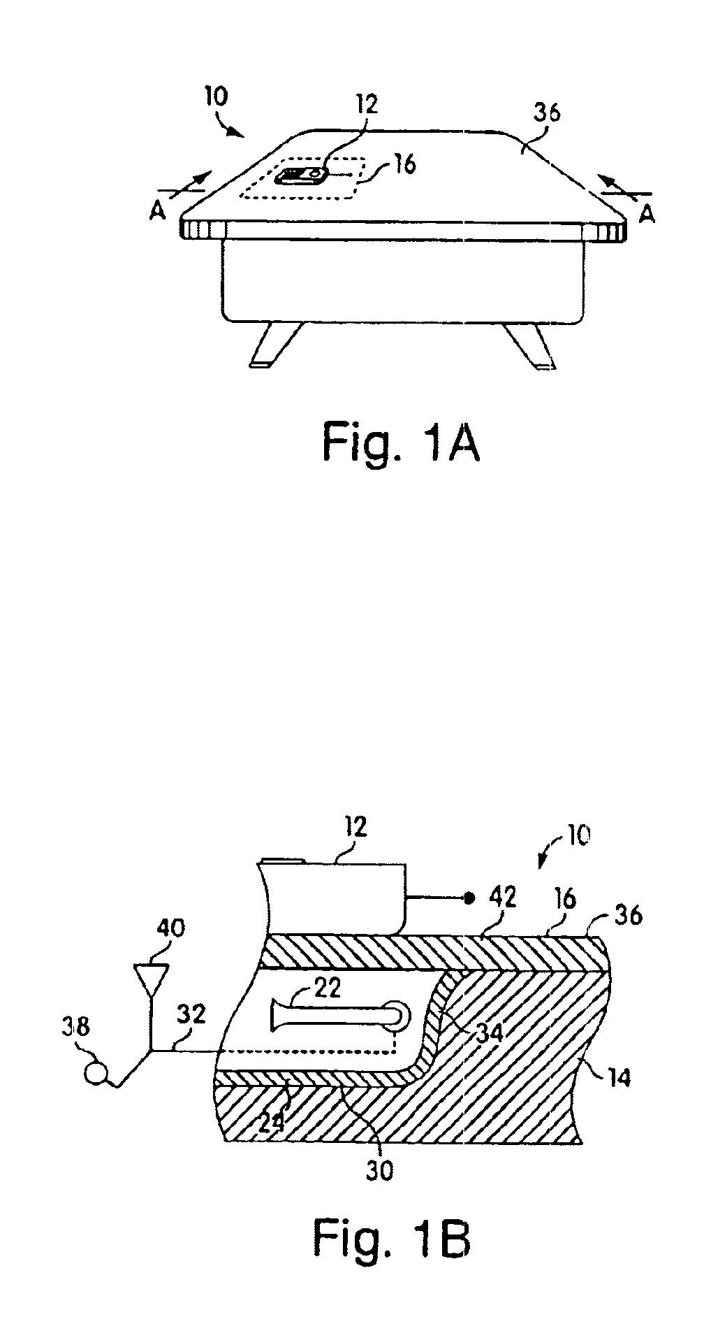
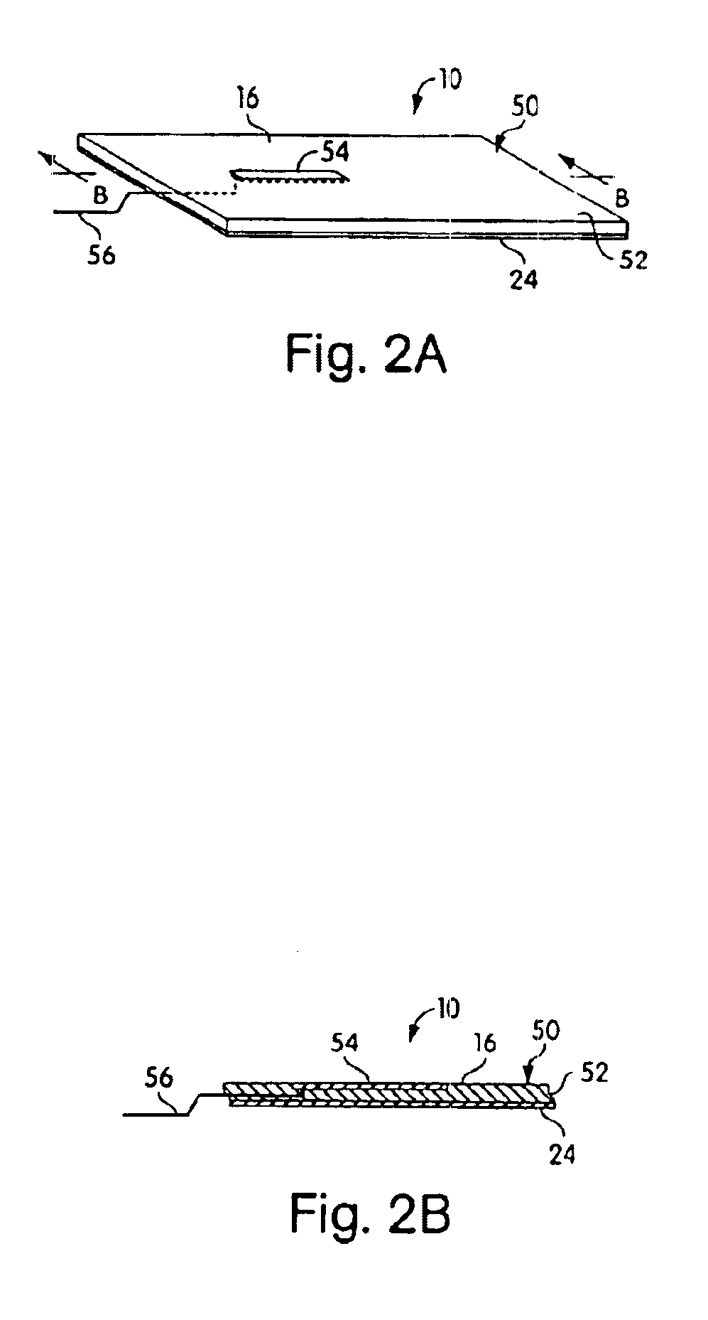
[0024]Referring now to the drawings in detail, and particularly to FIG. 1a, there is shown a portable communication device docking arrangement 10, to permit a portable communication device such as a hand-held cellular telephone 12 to be utilized thereon, such as on a desk 14 or adjacent to it, and as a personal communicator (i.e. cellular telephone, facsimile machine, pager or the like) which may also be carried on an individual.

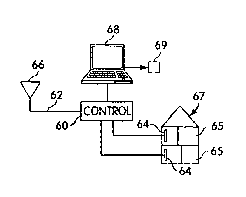
[0025]Such a docking system 10 of the present invention may also be adaptable to an automobile, plane, or building for providing radiationally restrictive communication between a portable electronic communication device 12 such as a cellular telephone, portable computer, facsimile machine, pager, or the like, while allowing communicative mating of the radiative antenna of that device to a further transmission line and communication system and / or a more remote antenna, as recited and shown in our aforementioned patent applications, incorporated herein by refe...


PUM


Abstract

A method of providing wireless communication to a personal communication device in an rf restricted environment. The personal communication device has a radiative antenna. The method comprising: providing a personal communication device with a radiative antenna; providing a first coupler antenna within the rf restricted environment; connecting the first coupler antenna to a second antenna mounted on the outside of the rf restricted environment through a computer controlled circuit arranged therebetween; wirelessly connecting the first coupler antenna with the radiative antenna of the personal communication device within the rf restricted environment; monitoring communications of the personal communication device at any point between the first coupler antenna and the second antenna; and billing for use of the personal communication device within the rf restricted environment. The personal communication device may be a cellular telephone. The personal communication device may be a laptop computer. The rf restricted environment may be an airplane.

Description

[0001]This application is a continuation of application Ser. No. 08 / 604,105 filed Feb. 20, 1996 and a continuation-in-part of application Ser. No. 09 / 009,220 filed Jan. 20, 1998, now U.S. Pat. No. 6,112,106 which are CIP's of Ser. No. 08 / 581,065 filed Dec. 29, 1995, now U.S. Pat. No. 5,711,014 and Ser. No. 08 / 042,879 filed Apr. 5, 1993, now U.S. Pat. No. 5,493,702 each incorporated herein by reference.BACKGROUND OF THE INVENTION[0002](1) Field of the Invention[0003]This invention relates to a docking system for handheld electronic communication devices such as cellular telephones or the like, for use with structures or vehicles, and is a Continuation-In-Part Application of U.S. patent application, Ser. No. 08 / 581,065, filed Dec. 29, 1995, which is a Continuation-In-Part Application of our allowed co-pending U.S. patent application Ser. No. 08 / 042,879, filed Apr. 5, 1993, each being incorporated herein by reference, in their entirety.[0004](2) Prior Art[0005]Extraneous radio frequenc...

Claims


Application Information

Patent Timeline
IPC IPC(8): H01Q1/24H04B1/38
CPCH01Q1/241H04B1/3877H01Q1/243H04B1/3833
Inventor CROWLEY, ROBERT JHALGREN, DONALD N.
Owner AMBIT ENERGY
Learn More