Magnetic resonance imaging method and device

a magnetic resonance imaging and magnetic field technology, applied in the field of magnetic resonance imaging (mri) methods and apparatuses, can solve the problems of static magnetic field non-uniformity correction methods that do not work effectively, static magnetic field non-uniformity is varied, and data for static magnetic field non-uniformity correction previously measured does not include the change of static magnetic field non-uniformity by the motion of objects. , to achieve the effect of high quality imag

Inactive Publication Date: 2005-04-26
HITACHI MEDICAL CORP
View PDF4 Cites 30 Cited by
  • Summary
  • Abstract
  • Description
  • Claims
  • Application Information

AI Technical Summary

Problems solved by technology

This is a problem in the image.
This artifact appears to be a false image as if image is flowing through the whole screen, and it is a big obstacle in a clinical diagnosis.
By the way, in case of continuously imaging a region close to breast such as heart or lung field, if said motion correction method is performed together with said static magnetic field non-uniformity correction method, there is a case that static magnetic field non-uniformity correction method does not work effectively.
That is, by the influence of the motion accompanied with breath motion of the object, static magnetic field non-uniformity is varied, too.
However, data for static magnetic field non-uniformity correction previously measured does not include the change of static magnetic field non-uniformity by the motion of the object.
So it is impossible to correct the measured echo signal accurately, even if static magnetic field non-uniformity correction is performed.

Method used


Image

  • Magnetic resonance imaging method and device
  • Magnetic resonance imaging method and device
  • Magnetic resonance imaging method and device

Examples


first embodiment

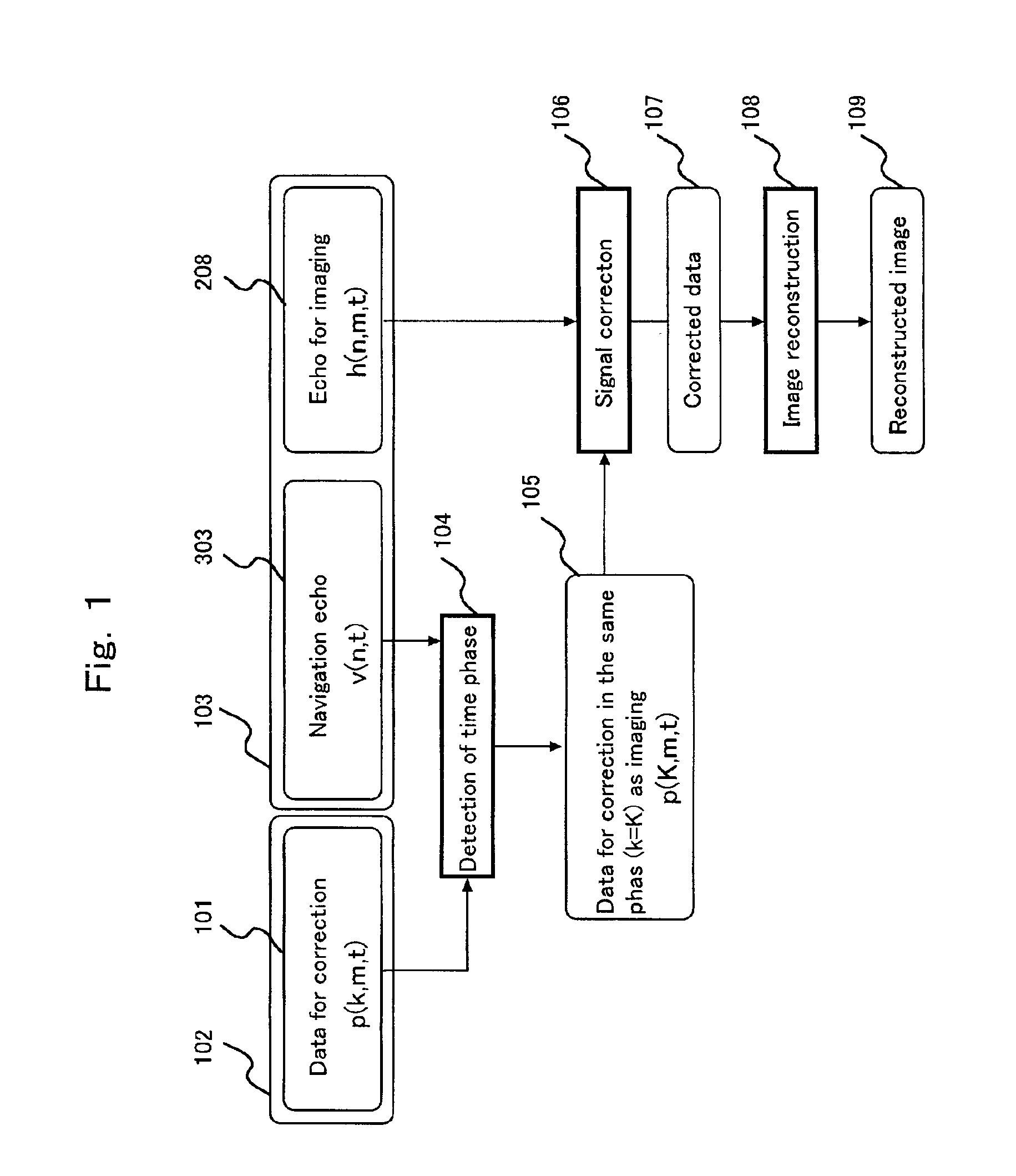
[0030]Next, a method for imaging continuously the plural number of images in the MRI apparatus of these compositions will now be explained. FIG. 1 is a view illustrating first embodiment of the invention. This imaging method comprises step 102 for acquiring signal for correcting static magnetic field non-uniformity, step 103 for acquiring echo for imaging, and step 104, 106, 108 for signal processing and image reconstruction using these signals. At first after performing preliminary measurement before imaging of the object, correction signal for removing influence of static magnetic field non-uniformity from measured signal for imaging.

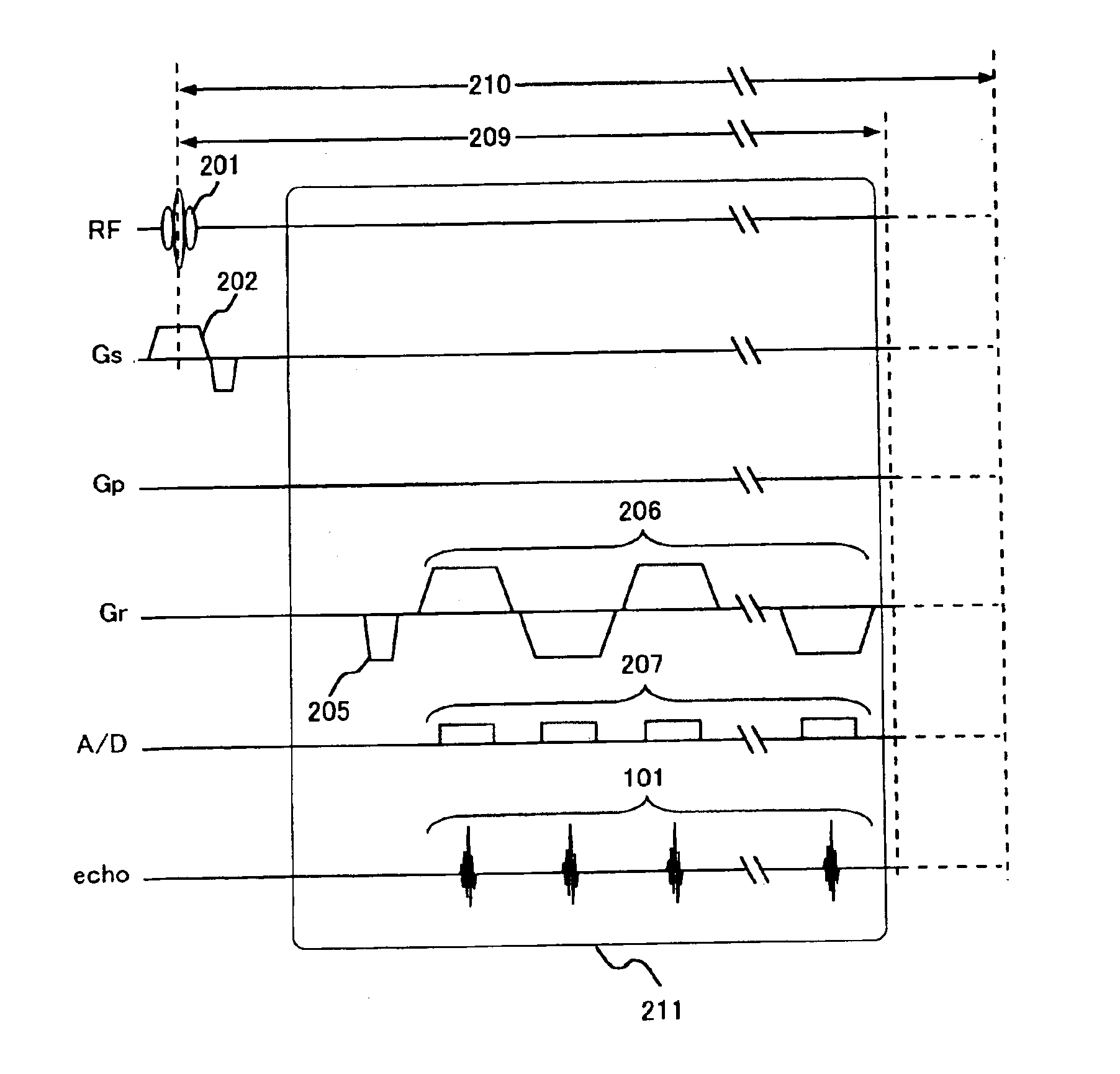
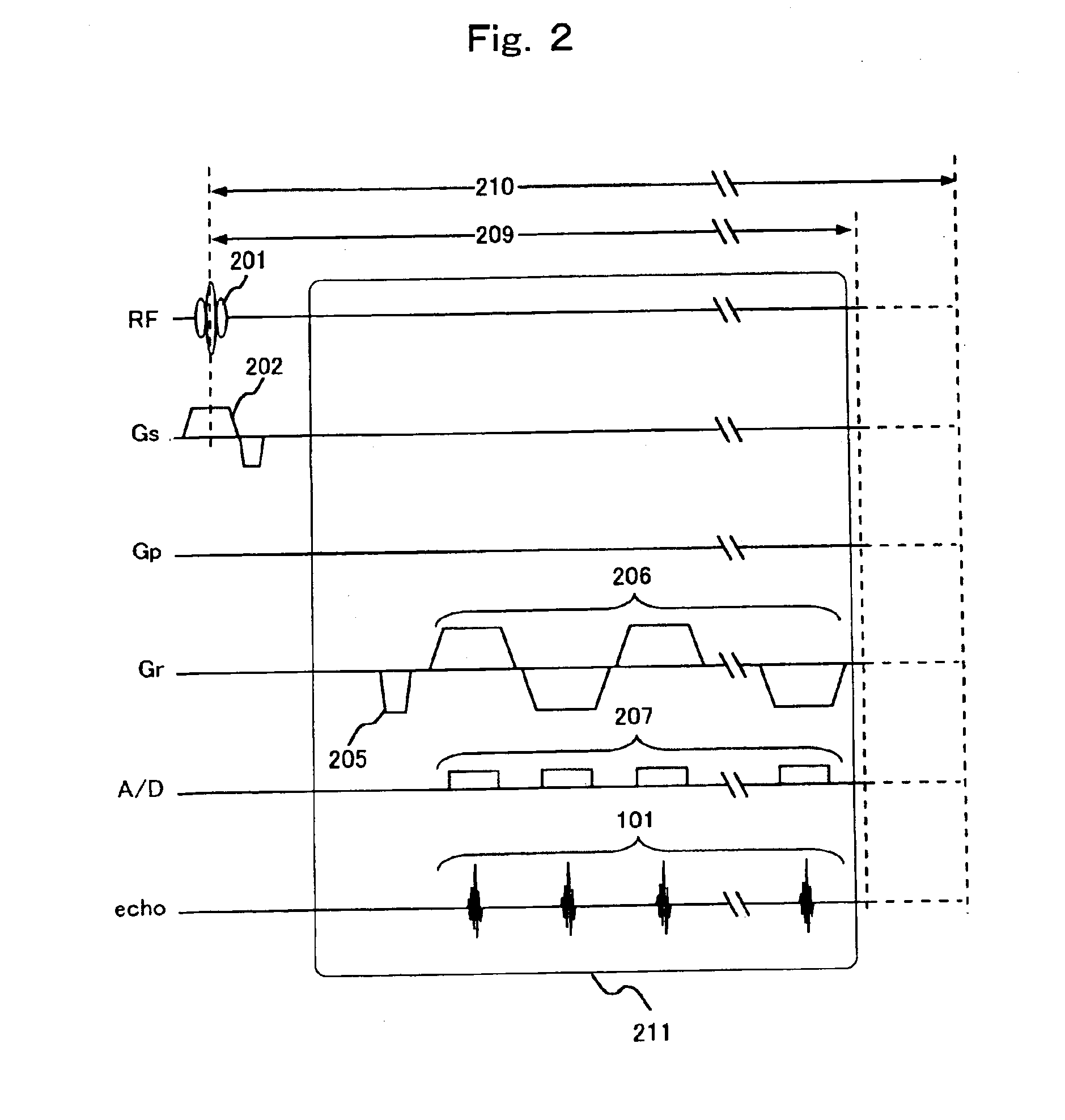
[0031]FIG. 2 is view illustrating one example of pulse sequence for acquiring signal 101 for correcting static magnetic field non-uniformity by step 102 in FIG. 1. This pulse sequence is based on multi-shot type EPI sequence. But pulse sequence shown in FIG. 2 is different from EPI sequence that is performed later, in the point that it measures plural...

third embodiment

[0051]Furthermore, the present invention will be explained using FIG. 9. This embodiment is also the same as the embodiment shown in FIG. 7 in the point that has step 702, 703 acquiring data set including navigation echo in both preliminary measurement and imaging. But the difference with an embodiment in FIG. 7 is that it has a motion correction step 903 before signal correction step 106.

[0052]In this embodiment, in the step 704 to detect time phase by comparing navigation echo 701 in the preliminary measurement with navigation echo 303 in imaging, correction data p (K, m, t) 105 which is the same time phase as the imaging echo h (K, m, t) that should be corrected is outputted, together navigation echo pv (K, m, t) that is the same time phase as the imaging data 208 is outputted. From this navigation echo 901 and navigation echo 303 that is measured in the same repetition as the imaging echo, signal change by the motion of the object is obtained (step 902). And by using this change...


PUM


Abstract

A magnetic resonance imaging apparatus has means for detecting the movement of an object so as to correct the variation of the non-uniformity of static magnetic field because of the movement of the object and thereby to improve the quality of the MR image. When actually measured data is corrected by using a signal for correcting the static magnetic field obtained in a preliminary measurement, the influence of the non-uniformity of static magnetic field is eliminated from the image based on the information from the body movement detecting means by using a correcting signal measured at the same time phase of the periodic movement as that of the actually measured signal. A navigation echo measured during the same repetition time as that of the actually measured signal is used for detection of time phase by detecting means. As a result, the quality of image is not deteriorated by the variation of the non-uniformity of static magnetic field due to the movement of the body of the object, realizing imaging of high quality image.

Description

FIELD OF THE INVENTION[0001]The present invention relates to magnetic resonance imaging (MRI) method and apparatus for measuring nuclear magnetic resonance signal (NMR signal) by making occurrence of nuclear magnetic resonance (NMR) phenomenon to atomic nucleus such as hydrogen or phosphorous in an object, and for imaging distribution of density or relaxation time of nuclear spin in said object, and especially to techniques that enable to perform effectively static magnetic field correction in case of imaging the object with motion.BACKGROUND OF THE ART[0002]MRI is an apparatus detecting NMR signals (echo signal) produced from the object by applying high frequency magnetic field to the object placed in the static magnetic field, and signal processing and imaging these signals. And high uniformity of the static magnetic field is demanded in order to get image of high quality. Especially in fast imaging method, such as single-shot type or multi-shot type of an echo planar imaging (EPI...

Claims


Application Information

Patent Timeline
Patent Type & Authority Patents(United States)
IPC IPC(8): A61B5/055G01R33/565G01R33/567G01R33/54A61B5/11
CPCA61B5/055G01R33/5676G01R33/56563A61B5/11G01R33/56509
Inventor TAKIZAWA, MASAHIROTAKAHASHI, TETSUHIKO
Owner HITACHI MEDICAL CORP
Why Eureka
Try Eureka