Method and apparatus for thermal analysis

a technology of thermal analysis and apparatus, applied in the field of methods, can solve the problems of large number of repetitive calculations or iterations, significant amount of time and resources required for iterative calculations, and the operator and/or the related equipment require a significant amount of time and effort, so as to achieve the effect of improving the efficiency of operation and reducing the number of repetitions

Inactive Publication Date: 2005-04-26
HONDA MOTOR CO LTD
View PDF5 Cites 8 Cited by
  • Summary
  • Abstract
  • Description
  • Claims
  • Application Information

AI Technical Summary

Benefits of technology

[0014]According to the method and the apparatus for thermal analysis of the present invention, since the heat transfer coefficients are automatically obtained repeatedly by computation, it is not necessary to select the experimental formula, whereby temperature distribution and the heat transfer coefficient can effectively be obtained. In addition, since the heat transfer coefficients and temperature distributions can be obtained continuously, the final temperature distribution and the heat transfer coefficient are obtained almost simultaneously, whereby operating efficiency improves.
[0015]Temperature distribution can be obtained by utilizing the heat transfer coefficients obtained by working out the simultaneous formula of approximate expressions for heat transfer coefficient, not by the experimental formula. Therefore, the convergence in differences can be obtained at the earlier timing, and the number of iterations until the final heat transfer coefficient and temperature distribution are obtained may be reduced.

Problems solved by technology

In the case where the experimental formula for calculating the heat transfer coefficient of the heat transfer boundary on which natural convection heat transfer occurs is automatically selected according to various conditions as described above, there exists a problem in that a large number of repetitive calculations or iterations are necessary for selecting an experimental formula suitable for a geometrical model of the object.
In addition, a large number of iterations are required for determining the heat transfer coefficient and both the operator and / or the related equipment require a significant amount of time and effort.
In addition, there also exists a problem in that an experimental formula is required for every geometric model of the target object to be analyzed.
In addition, a significant amount of time and resources are required to perform iterative calculations for determining the associated heat transfer coefficients.

Method used


Image

  • Method and apparatus for thermal analysis
  • Method and apparatus for thermal analysis
  • Method and apparatus for thermal analysis

Examples


Embodiment Construction

[0030]The present invention will hereinafter be described with reference to the accompanying drawings. Referring now to the embodiments, a method and an apparatus for thermal analysis according to the present invention will be described hereinafter.

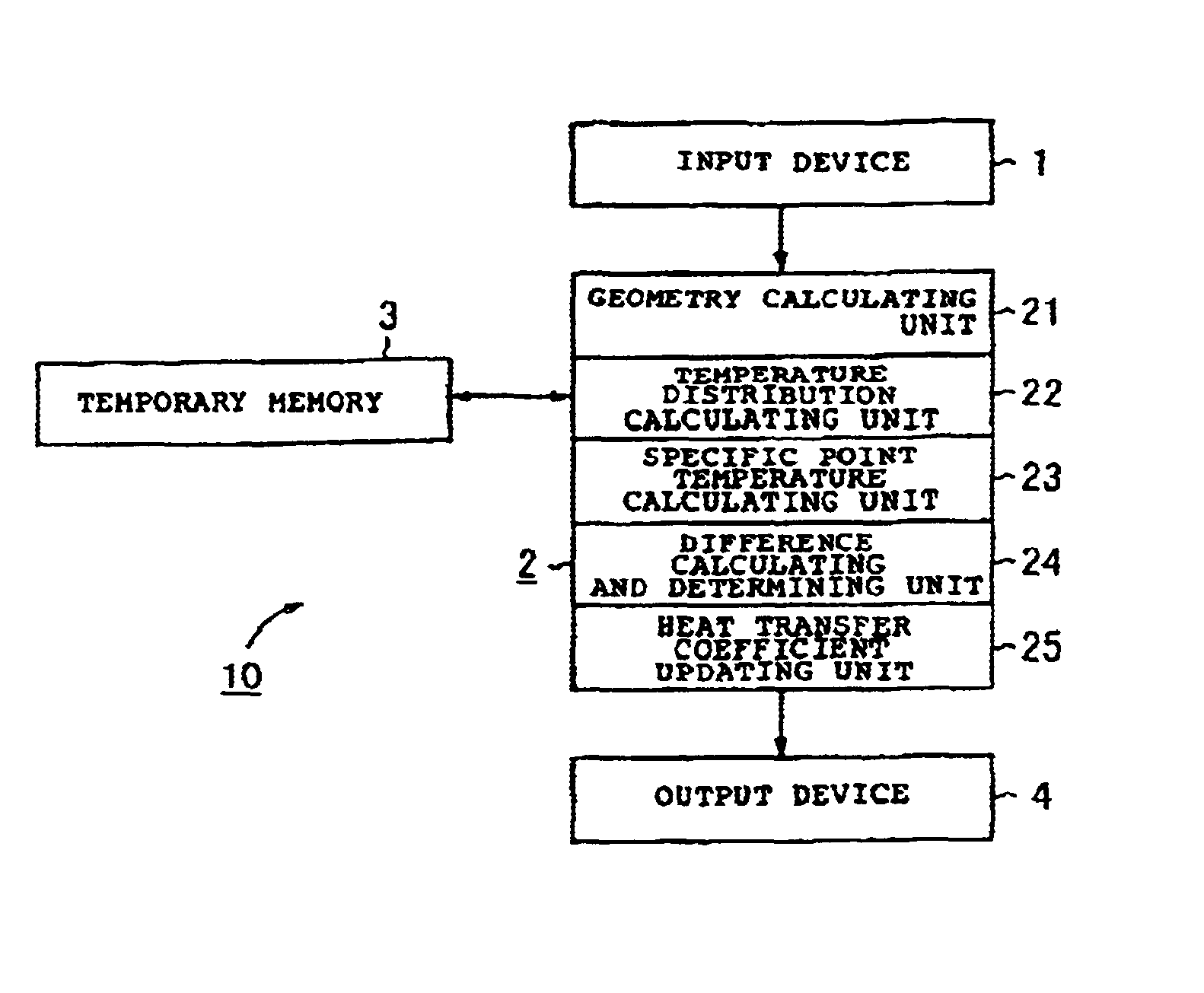
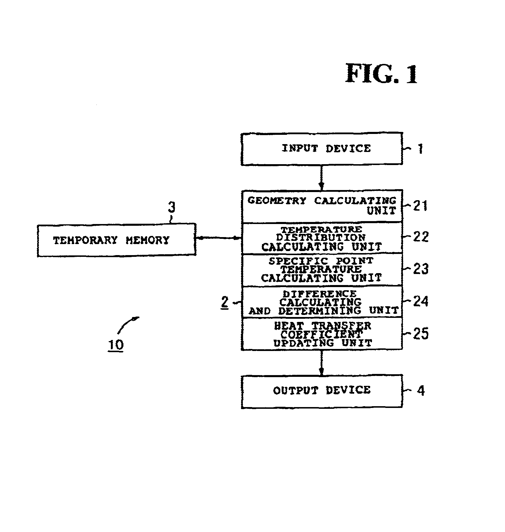
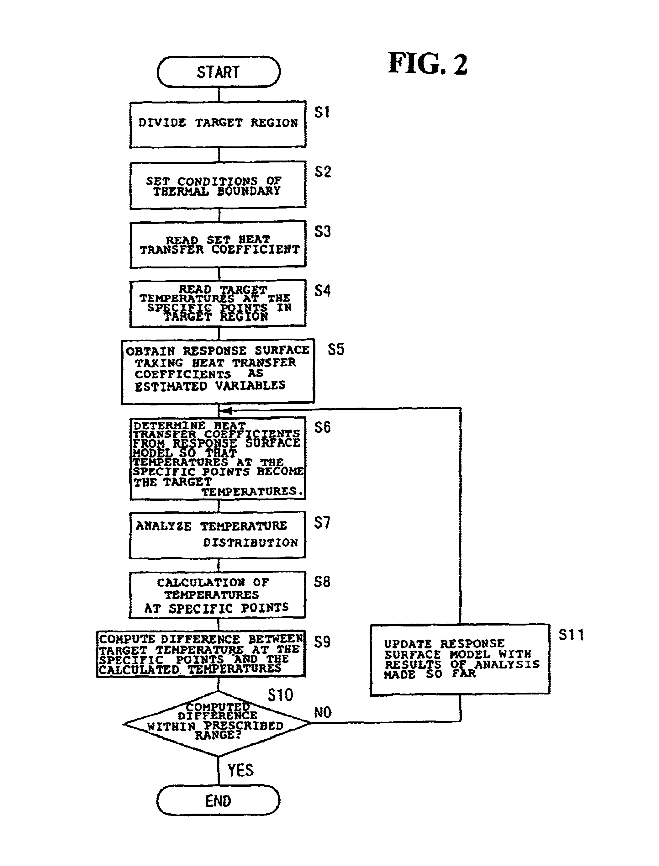
[0031]FIG. 1 is a block diagram of a thermal analysis apparatus according to one embodiment of the present invention. FIG. 2 is a flow chart describing a thermal analysis apparatus and method according to an embodiment of the present invention. FIG. 3 is a cross sectional view of a piston to which the thermal analysis apparatus is applied according to an embodiment of the present invention. FIG. 4 is a partial cross sectional view showing heat transfer coefficients in the thermal analysis apparatus according to an embodiment of the present invention. FIG. 5 is a sectional view showing temperature distributions obtained using the thermal analysis apparatus according to an embodiment of the present invention. FIG. 6 is a partial, sectional ...


PUM

PropertyMeasurementUnit
temperaturesaaaaaaaaaa
thermal analysisaaaaaaaaaa
temperature distributionaaaaaaaaaa

Abstract

In a method and an apparatus for thermal analysis, a target region is divided by dividing the geometry of the target object of the thermal analysis into a finite number of finite elements or cells. The thermal analysis on the target region is conducted using the results of the division. A temperature distribution on the target object is obtained from the heat transfer coefficients by a temperature distribution calculating unit. The actual temperatures at specific points are obtained based on temperature distribution obtained by the specific point temperature calculating unit. Differences between the actually obtained temperatures at the specific points and the predetermined target temperatures at the specific points are obtained by a difference calculating/determining unit. If the differences are determined to be out of the prescribed range, the heat transfer coefficients are changed by a heat transfer coefficient updating unit. These steps are repeated until the differences fall within the prescribed range so that temperature distribution on the target object is obtained. The method and apparatus for thermal analysis obtains temperature distribution universally, irrespective of geometries of the target object.

Description

CROSS-REFERENCES TO RELATED APPLICATIONS[0001]This nonprovisional application claims priority under 35 U.S.C. § 119(a) on Patent Application No. 2001-235556 filed in Japan on Aug. 2, 2001, the entirety of which is herein incorporated by reference.BACKGROUND OF THE INVENTION[0002]1. Field of the Invention[0003]The present invention relates to a method and an apparatus that can be utilized for thermal analysis, e.g., for analyzing temperature distribution across a piston in an internal combustion engine, and more specifically, to a method and an apparatus for thermal analysis using a response surface method.[0004]2. Description of the Background Art[0005]When performing thermal analysis, e.g., as shown in Japanese Patent Document JP-A-11-118740, the entire contents of which are hereby incorporated by reference, an experimental formula for calculating a heat transfer coefficient of a heat transfer boundary on which natural convection heat transfer occurs is automatically selected depen...

Claims


Application Information

Patent Timeline
Patent Type & Authority Patents(United States)
IPC IPC(8): G01N25/18G06F17/12G06F17/18
CPCG01N25/18
Inventor OGINO, TAKASHIMURAKAMI, HIROTAKA
Owner HONDA MOTOR CO LTD
Why Eureka
Try Eureka