System for transferring a fluid product between a carrying vessel and a shore installation

a technology for transferring systems and fluid products, applied in passenger handling apparatuses, special-purpose vessels, packaged goods types, etc., can solve the problems of increasing installation costs, cumbersome environment, and complex transfer stations and their environmen

Inactive Publication Date: 2005-05-03
SOC EURO DINGENIERIE MECANIQUE EURODIM SA
View PDF6 Cites 42 Cited by
  • Summary
  • Abstract
  • Description
  • Claims
  • Application Information

AI Technical Summary

Benefits of technology

[0004]To solve this problem, a transfer system of the invention is characterized in that it comprises at least one connection device to the manifold of the vessel and at least one flexible transfer pipe connected to the shore installation, and in that the connection device and flexible pipe are able to be connect

Problems solved by technology

This type of transfer station is globally satisfactory but has the major disadvantage of tending to make transfer stat

Method used


Image

  • System for transferring a fluid product between a carrying vessel and a shore installation
  • System for transferring a fluid product between a carrying vessel and a shore installation
  • System for transferring a fluid product between a carrying vessel and a shore installation

Examples


first embodiment

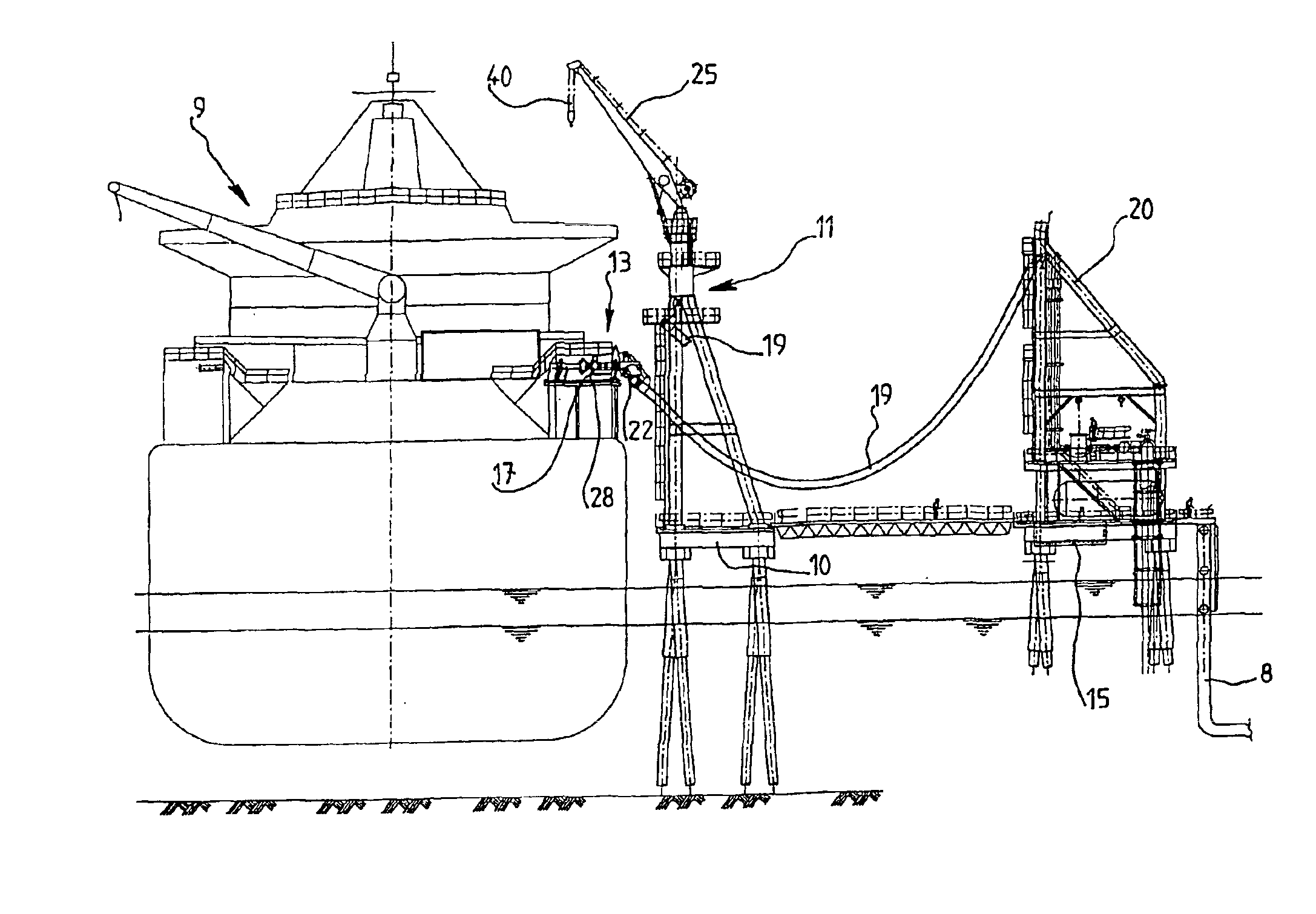
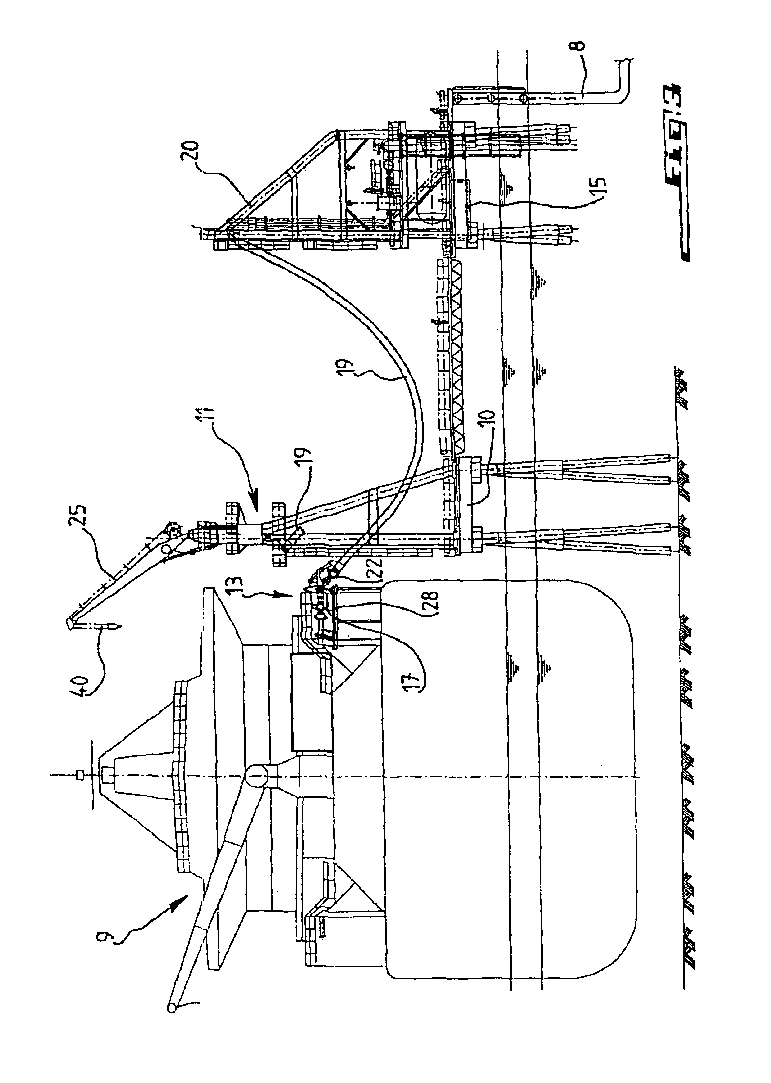
[0060]With reference to FIGS. 6 to 8, the structure of a transfer arrangement 13 of the invention is now described in more detail.

[0061]The connection module 17 of this arrangement, between its fixing connector 16 to the vessel's manifold flange 18 and the support or bearing device 30 on the vessel's manifold platform 28, comprises a bellows joint device 33 to insulate the manifold flange from forces of the flexible pipe at the time of its connection to the manifold when it leans on the manifold platform. The adjustable bearer device 30 is connected to the module via an articulation having a horizontal axis 34. Optionally an additional articulation (not shown)may be used to allow rotations along the axis of the manifold. As can be seen in FIG. 8, the bearer 30 comprises two adjustable supporting struts 30 bearing a crosspiece 38 which carries piping 32. In addition to bearer 30, the module is provided with an adjustable foot 35 positioned at the bellows joint 33 and intended to prov...

third embodiment

[0071]FIGS. 11 to 14 illustrate a third embodiment which is particular in that the connector provided for coupling the connection module to flexible pipe 19 as well as the emergency disconnection device are provided on the end of the flexible pipe. The connector and the disconnection device are respectively denoted 65 and 66. As shown in the figures, the structure of the connection module now denoted 67 is simplified. This module 67 comprises part of a tubular transfer structure which contains a central sleeve 69 connected at one end to a bellows joint 70 carrying a hydraulic or manual connector 71 for attachment to the vessel's manifold flange 18 and at its other end a bellows joint 72 carrying a flange 74 to receive connector 65 of the flexible pipe. Sleeve 69 is mounted via a vertical part 75 and a horizontal part 76 forming the alignment trumpet on a supporting frame 77 via which the module rests on the vessel's manifold platform 28. This frame 77 essentially comprises a ring 79...

fifth embodiment

[0076]FIG. 16 shows a fifth embodiment which is particular in that the part denoted 105 which carries connector 106 of the end of the flexible pipe is offset sideways relative to the axis of the flexible pipe 19 while extending substantially parallel to its axis. On the other hand the trumpet denoted 107 and cone 108 now extend along the axis of the flexible pipe.

[0077]FIG. 17 illustrates another possible implementation of the transfer system of the invention whose particular feature is that the part of the connection arrangement of the invention, which in FIG. 11 for example corresponds to the connection module, is now integrated with the end portion denoted 110 of the manifold and it is only the mouthpiece 111 of flexible pipe 19 which can be moved being suspended from gantry 11. Therefore part 111 of the manifold carries the alignment device to fix mouthpiece 111 of the flexible pipe to manifold flange 112, namely the alignment trumpet 113, winch 114 and return pulley 115 of cabl...


PUM

PropertyMeasurementUnit
Flexibilityaaaaaaaaaa

Abstract

A system for transferring a fluid product between a carrier, such as a vessel, and an installation, in particular a fixed installation, for processing and storing the product. The system includes a tubular structure for conveying the product between the vessel and the installation, a device for connection to a manifold of the vessel and a flexible transfer pipe connected to the installation. The connection device and the pipe are connectable to each other at free ends for transferring the fluid product between the vessel and the installation. At least the free end of the flexible transfer pipe includes a product handler for displacing the free end between a position for connection to the connection device and a disengaged position for storage. The invention enables the transfer of cryogenic liquefied natural gas.

Description

[0001]The invention concerns a system for transferring a fluid product, in particular liquefied natural gas, between a carrying vessel, such as a ship, and an installation, especially a shore installation, for processing and storing the product, of the type comprising a tubular arrangement to convey the product between the vessel and the installation, of which one end is connected to the installation and the other end is connectable to the vessel's manifold.[0002]Transfer systems of this type exist for transferring liquefied natural gas. FIG. 1 shows a conventional transfer station for LNG (liquefied natural gas) generally illustrated under reference 1 and comprising a platform 2 on which loading or unloading arms 3 are mounted formed of rigid piping and structures articulated with one another via multiple rotating joints. The transfer station is associated with a mooring installation 4 for vessels to be loaded or unloaded via transfer station 1. The latter is located at the end of ...

Claims


Application Information

Patent Timeline
IPC IPC(8): B67D9/00
CPCB67D9/00
Inventor DUPONT, BERNARDPAQUET, STÉPHANE
Owner SOC EURO DINGENIERIE MECANIQUE EURODIM SA
Why Eureka
Try Eureka