High pressure fluid cylinder system

a fluid cylinder and high-pressure technology, applied in the direction of liquid fuel engines, sealing/packing, borehole/well accessories, etc., can solve the problems of system components under extreme stress, and achieve the effect of reducing the likelihood of cocking and light weigh

Inactive Publication Date: 2005-05-03
NEW LANTAO BUS
View PDF4 Cites 17 Cited by
  • Summary
  • Abstract
  • Description
  • Claims
  • Application Information

AI Technical Summary

Benefits of technology

[0004]It is desirable to increase the operating pressure of the systems so that the various operations can be performed more efficiently. However, due in part to the cyclical operation between high and low pressure, the system components undergo extreme stresses. The life span of the components may therefore be reduced as in relation to the increase in system pressure.
[0009]When the pressure within the fluid pumping chambers reaches a predetermined pressure, a discharge valve overcomes a discharge spring and water pressure within the discharge passage. The discharge valve is of relatively light weight and includes a multiple of wing guides which reduce the likelihood of cocking as fluid exits the fluid pumping chambers and enters the manifold. The fluid exits through the discharge passage and the discharge port and travels out to the gun.

Problems solved by technology

However, due in part to the cyclical operation between high and low pressure, the system components undergo extreme stresses.

Method used


Image

  • High pressure fluid cylinder system
  • High pressure fluid cylinder system
  • High pressure fluid cylinder system

Examples


Embodiment Construction

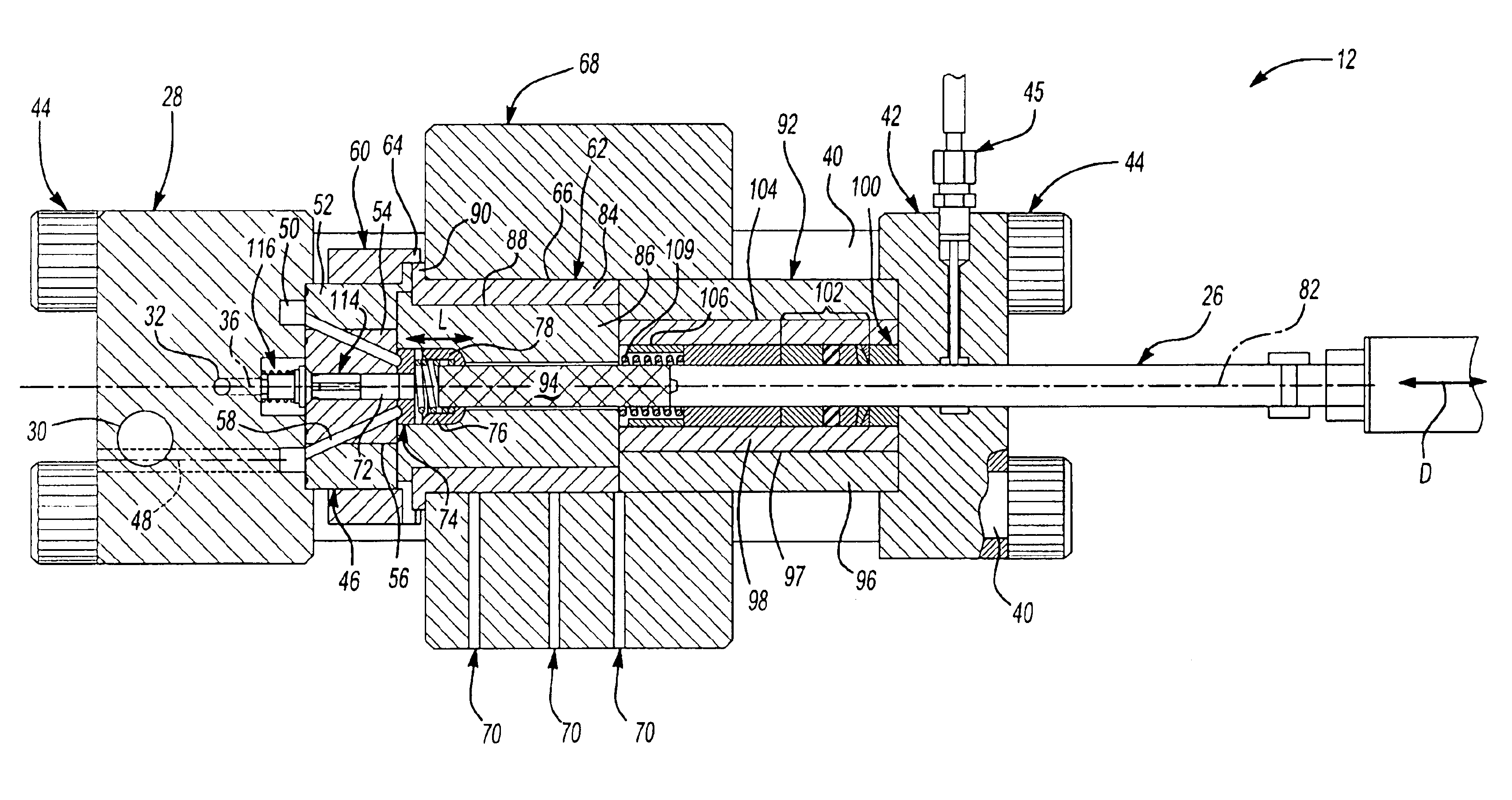
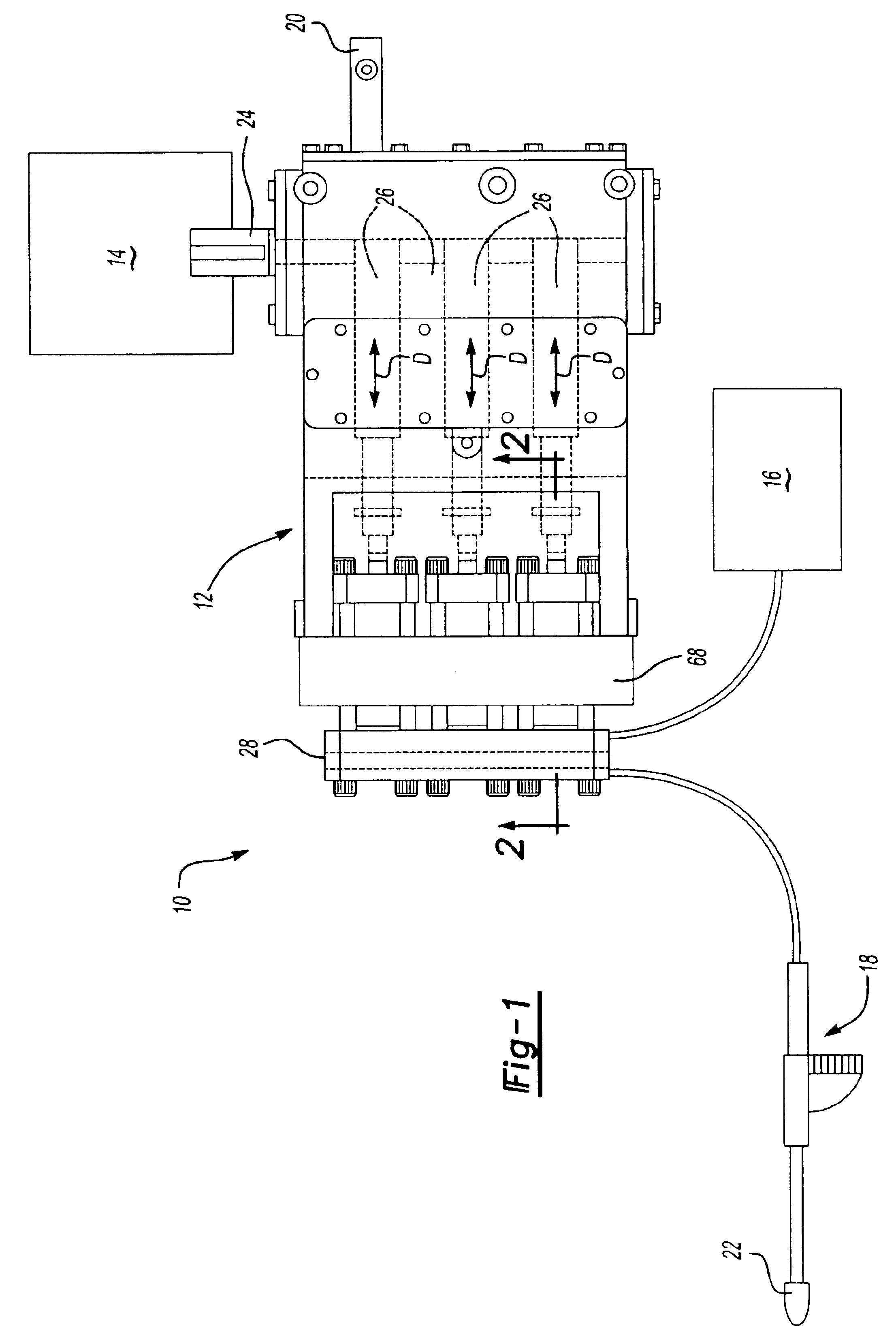
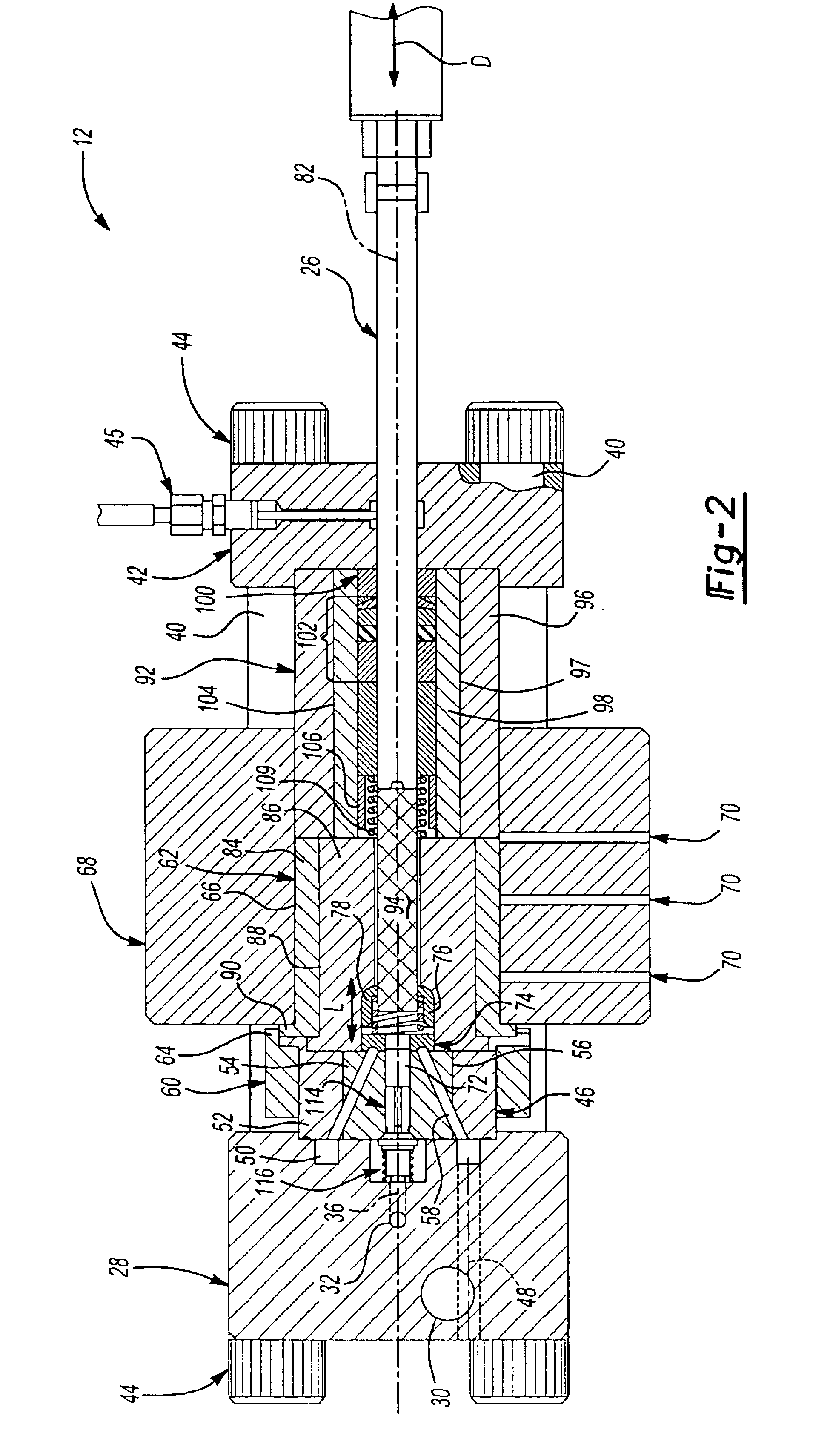
[0023]FIG. 1 illustrates a high pressure fluid jetting system 10. The system 10 generally includes a fluid cylinder pump 12, a drive assembly 14, a pressurized liquid supply 16 and an applicator gun 18. Preferably, the fluid cylinder pump 12 operates to selectively jet water from the gun 18 at a pressure of approximately 50,000 psi and 10.0 gallons per minute. A by-pass valve 20 provides for fine-tuning of the system pressure.

[0024]The drive assembly 14 includes a diesel or electric powered motor which drives a rotatable drive shaft 24. Drive shaft 24 drives a triple plungers 26 which are reciprocally driven in the direction of doubled headed arrows D. Plungers 26 communicate fluid from the supply 16 to the gun 18, such that the fluid is discharged form the nozzle 22 at a pressure of approximately 50,000 psi. As the nozzle 22 of the gun 18 wears, by pass valve 20 may be adjusted automatically or manually such that the fluid pressure is maintained at approximately 50,000 psi. The 50,...


PUM


Abstract

A high pressure fluid jetting system generally includes a fluid cylinder pump, a drive assembly, a pressurized liquid supply and an applicator gun. The drive assembly includes a diesel or electric powered motor which drives a rotatable drive shaft. The drive shaft drives a triple plunger which are reciprocally driven. The plungers communicate fluid from the supply to the gun to selectively jet water from the gun at a pressure of approximately 50,000 psi and 10.0 gallons per minute.

Description

BACKGROUND OF THE INVENTION[0001]The present application claims priority to U.S. Provisional Patent Application Ser. No. 60 / 257,795, filed 22 Dec. 2000.[0002]The present invention relates to a high pressure fluid cylinder, and more particularly to a multiple of interference fit components which provide dependable operation of a fluid cylinder at approximately 50,000 psi and 10 gpm.[0003]Systems which perform water jetting operations such as surface preparation, cutting cleaning, coating removal and other operations are known. The systems typically use a fluid cylinder having reciprocating plungers to force the fluid out of an applicator at extremely high pressure. As the plungers reciprocate within the fluid cylinder, the fluid cylinder and components thereof cycle between atmospheric and maximum system pressure.[0004]It is desirable to increase the operating pressure of the systems so that the various operations can be performed more efficiently. However, due in part to the cyclica...

Claims


Application Information

Patent Timeline
Patent Type & Authority Patents(United States)
IPC IPC(8): B05B9/04F04B53/16F04B53/10F04B53/00
CPCB05B9/0413F04B53/164F04B53/103F04B53/10
Inventor FORREST, JAMIE A.
Owner NEW LANTAO BUS
Why Eureka
Try Eureka