

Hydraulic suspension strut for an amphibious vehicle
a technology for amphibious vehicles and suspension struts, which is applied in the direction of propulsive elements, loading-carrying vehicle superstructures, understructures, etc., can solve the problems of bulky mechanical retraction systems listed above and prone to corrosion
- Summary
- Abstract
- Description
- Claims
- Application Information
AI Technical Summary
Benefits of technology
Problems solved by technology
Method used
Image

Examples
Embodiment Construction
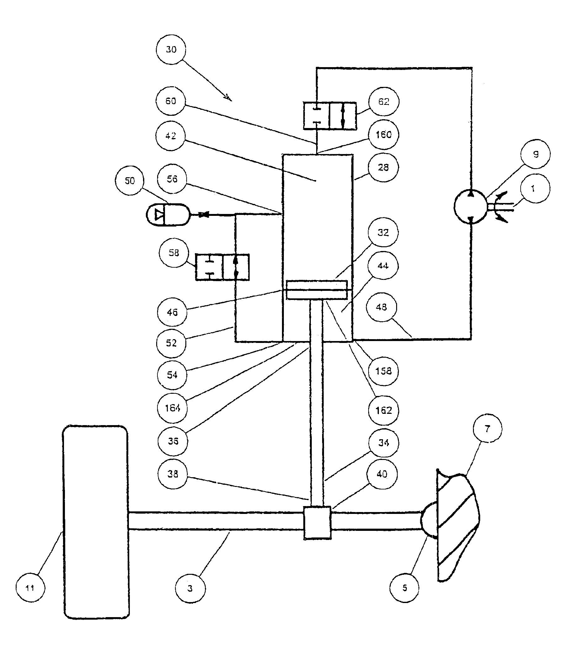
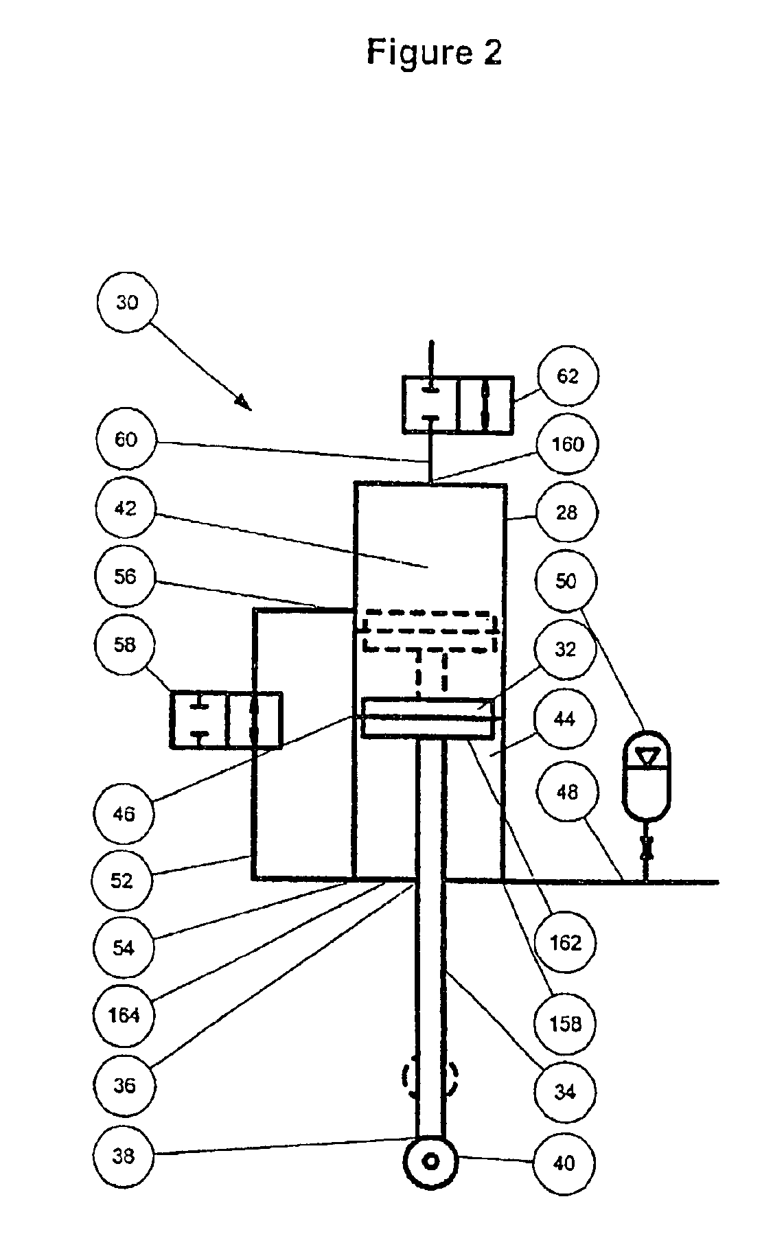
[0054]A hydraulic transfer line 52 is provided external to the cylinder 28 and connects first and second ports 54, 56 in the side wall of the cylinder. The first port 54 is located in the side wall close to the base of the cylinder 28, whilst the second port 56 is located in the side wall at approximately the mid-point of the cylinder 28. A first on / off valve 58 is provided in the transfer line 52.
[0055]In an alternative embodiment, the first port 54 could be provided in the end wall at the base of the cylinder.
[0056]A further hydraulic line 60 extends from a port 160 in the upper wall of the cylinder 28 and is controlled by a second on / off valve 62. The further line 60 is connected to the hydraulic system of the vehicle.
[0057]In use, a wheel (not shown) is linked to the linkage rod 34 via the mount 40 and the cylinder 28 is attached to the vehicle body (not shown).
[0058]In road travel mode, as the wheel encounters irregularities in the road surface on which the vehicle provided wit...
PUM
 Abstract
Description
Claims
Application Information