Connector, electronic equipment and control method for electronic equipment

a technology of electronic equipment and electronic equipment, applied in the direction of coupling device connection, circuit inspection/indentification, transportation and packaging, etc., can solve the problems of limited area, complicated operation, and increased operation functions

Inactive Publication Date: 2005-05-03
PIONEER CORP
View PDF16 Cites 16 Cited by
  • Summary
  • Abstract
  • Description
  • Claims
  • Application Information

AI Technical Summary

Benefits of technology

[0015]In this connector, the separation of the terminal from the shorter electrode occurs earlier than other electrodes. Thus, it becomes possible to detect detachment of the connector before other connections are disengaged.
[0021]In this connector, the connector has the terminals and electrodes arranged in a staggered manner along the direction at right angles to the sliding direction. Accordingly, it is possible to secure a large space for forming the terminals, whereby the connecting portions at high density can be formed. At least one of the electrodes is the separation detecting electrode formed shorter in the longitudinal direction.
[0027]In this electronic equipment, when the electronic equipment main body and the operation unit are separated, the power to the function portions for the operation unit is firstly cut off, and then the power to the control section is cut off. Accordingly, it is possible to make the initial settings of the function portions correctly to prevent a false display on the display part.
[0029]In this electronic equipment, the mechanism for regulating the sliding direction which is structured by the operation unit and the electronic equipment main body allows the separation detecting electrode to be disconnected before other electrodes are separated from the terminals, even though the connector does not comprise the sliding direction guide. Hence, it is possible to detect that the operation unit is disconnected before the other terminals are separated from the electrodes.
[0031]In this electronic equipment, since the operation unit is placed at a predetermined position forward from a panel of the electronic equipment main body, the user can operate the operation unit, and detach the operation unit from the electronic equipment main body more easily.

Problems solved by technology

In these car audio apparatus, operation functions tend to increase and the operation tends to become complicated, and many operation functions need be attached on an instrument panel, the area of which is limited.
Such the temporal differences cause a false display momentarily or an error in the initial settings.

Method used


Image

  • Connector, electronic equipment and control method for electronic equipment
  • Connector, electronic equipment and control method for electronic equipment
  • Connector, electronic equipment and control method for electronic equipment

Examples


first embodiment

[0048

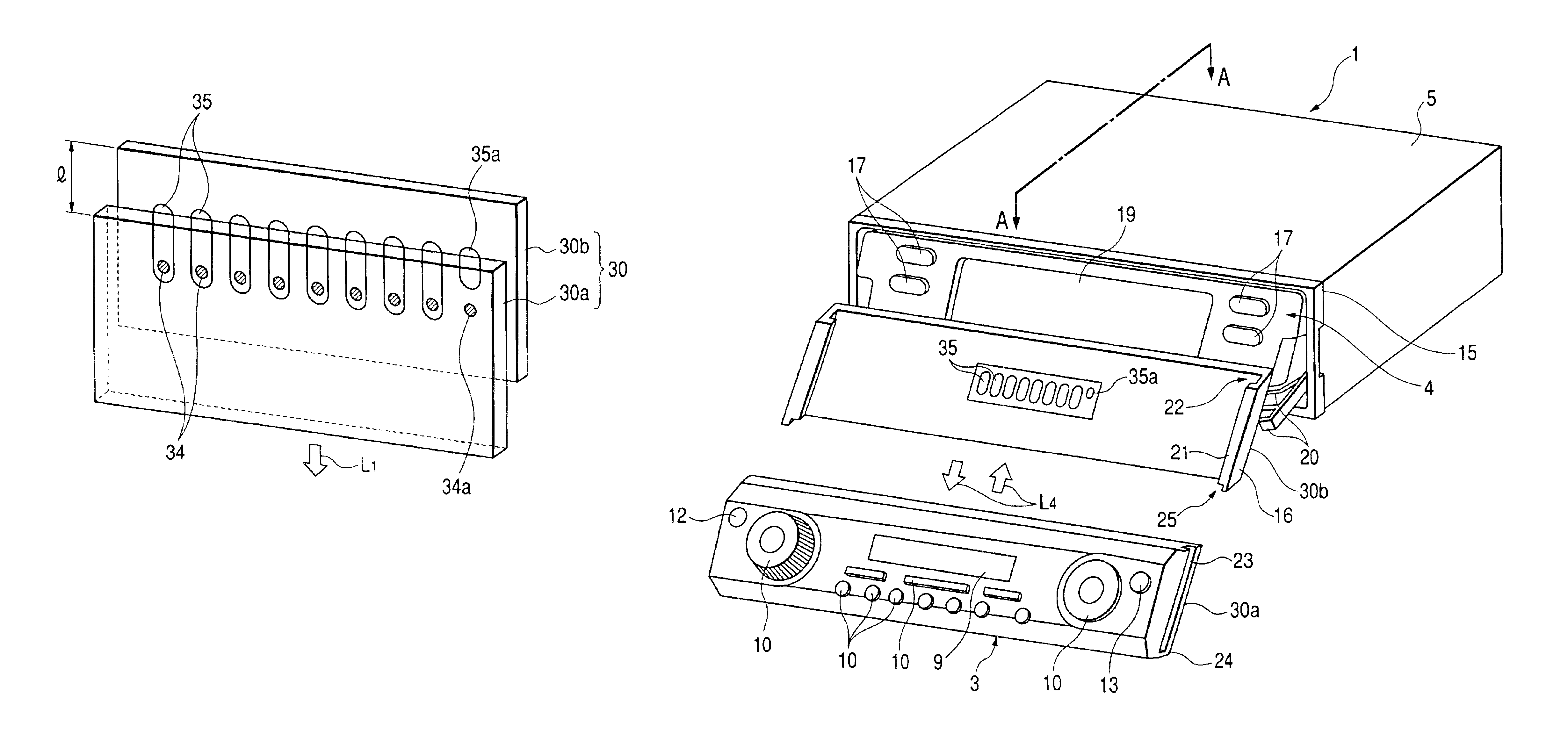
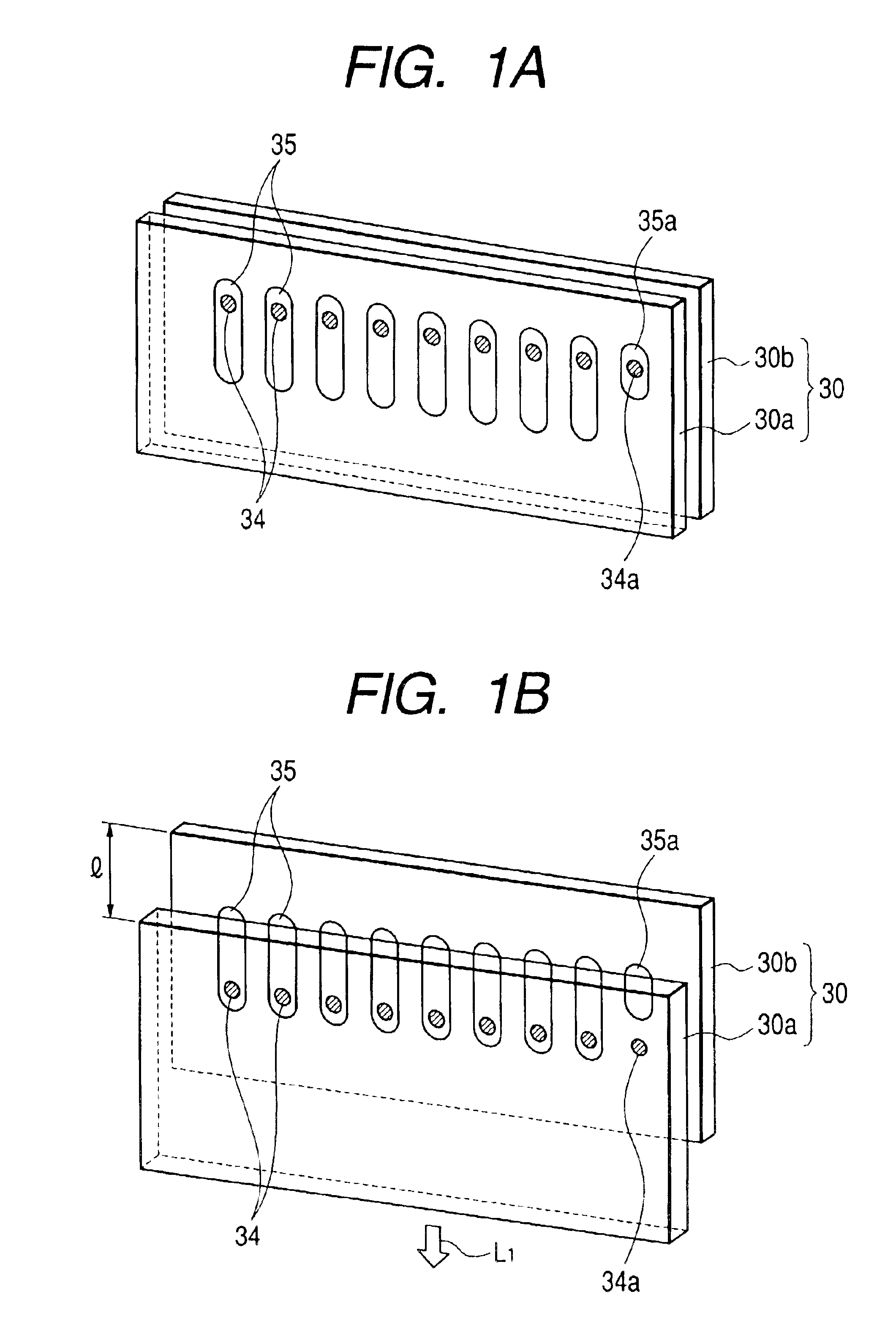
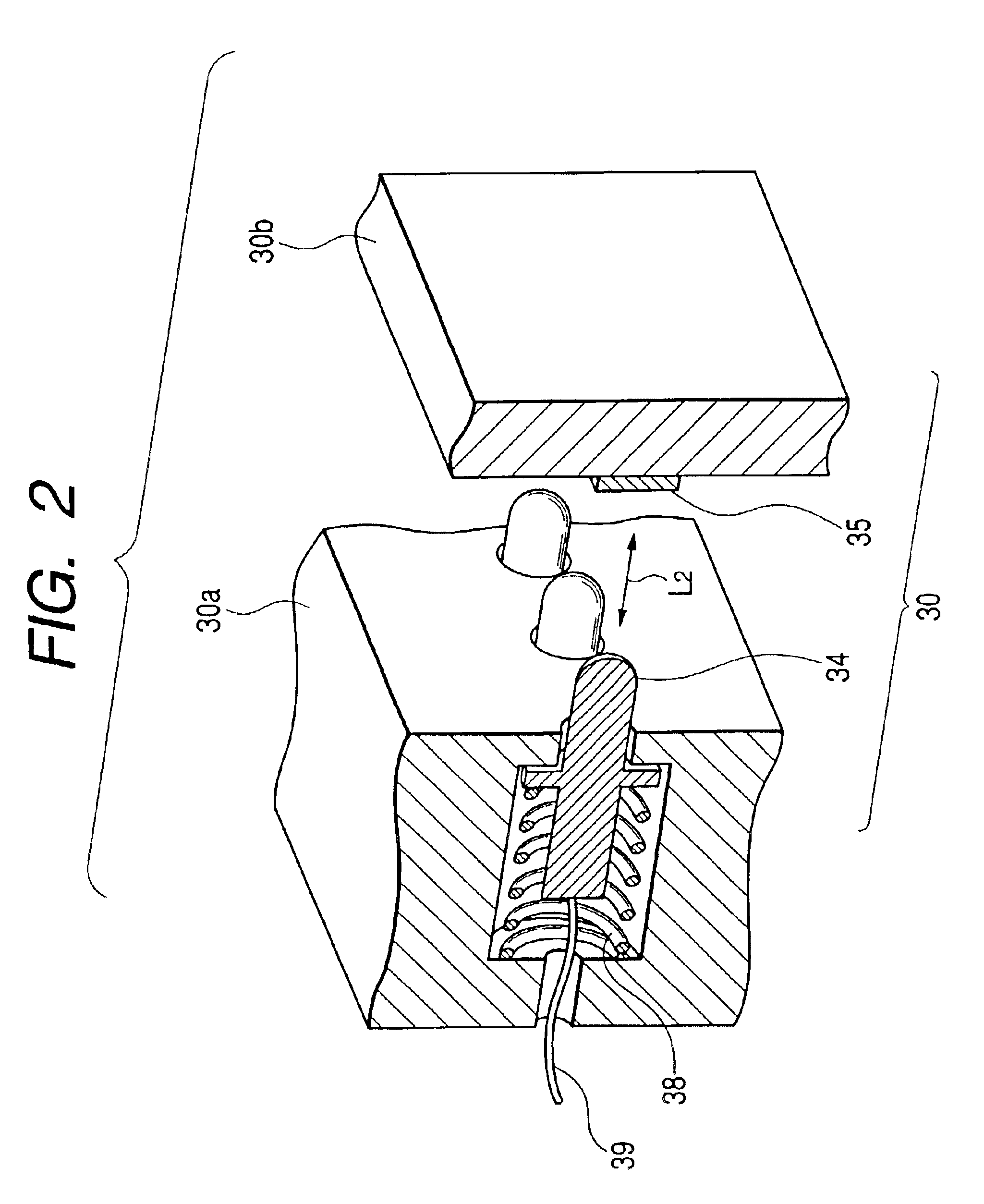
[0049]Referring to FIGS. 1A, 1B and 2, a first embodiment of the present invention will be described below. FIGS. 1A and 1B are perspective views showing an arrangement of electrodes and terminals of a connector according to a first embodiment. FIG. 1A shows a state where the connector is attached, and FIG. 1B shows a state where the connector is about to be detached. FIG. 2 is a partial cross-sectional view showing a configuration of the connector according to the first embodiment.

[0050]The connector 30 is suitably used for an electronic equipment having an operation unit detachable from an electronic equipment main body. The connector 30, for example, have a function of detecting detachment of the operation unit in order to cut off the power supplied to function portions such as a display unit provided in the operation unit before the power supplied to a CPU controlling the function portions is cut off, when the operation unit is detached from the electronic equipment main bo...

second embodiment

[0056

[0057]Referring to FIGS. 3A and 3B, a second embodiment of the invention will be described below. FIGS. 3A and 3B are perspective views showing another arrangement of electrodes and terminals of a connector according to the second embodiment. FIG. 3A is a state where the connector is attached, and FIG. 3B is a state where the connector is about to be detached.

[0058]As shown in FIG. 3, the connector 31 comprises an operation unit connector 31a that is fixed on an operation unit, and an electronic equipment main body connector 31b that is fixed on an electronic equipment main body. The operation unit connector 31a is provided with a plurality of terminals 36 made of a conductive material at regular intervals in a staggered arrangement. On the other hand, the electronic equipment main body connector 31b that is fixed on the electronic equipment main body is provided with a plurality of electrodes 37 at the positions corresponding to the terminals 36. Accordingly, if the operation ...

third embodiment

[0062

[0063]Referring to FIGS. 4 to 7, a third embodiment of the invention will be described below. In this embodiment, an electronic equipment comprises an electronic equipment main body and two operation units, in which an operation unit provided on the front portion is detachable from the electronic equipment main body. The electrical connection between the electronic equipment main body and the detachable operation unit is made using the connector as described in the first embodiment. However, the electrical connection may be made using the connector as described in the second embodiment.

[0064]FIG. 4 is a block diagram showing the configuration of the electronic equipment of the invention. FIG. 5 is a perspective view showing the electronic equipment. FIG. 6 is a perspective view showing the electronic equipment in an open state. FIG. 7 is a perspective view showing the electronic equipment in a state where the operation unit is detached. FIG. 8 is a partial cross-sectional side ...


PUM


Abstract

A connector has an operation unit connector that is fixed on an operation unit, and an electronic equipment main body connector that is fixed on an electronic equipment main body. The operation unit connector has plural terminals at regular intervals aligned in a row. The electronic equipment main body connector has plural electrodes at positions corresponding to the terminals at regular intervals. At least one of the electrodes is formed to be shorter than other electrodes and serves as a detecting electrode. The detecting electrode is disposed at the same upper position as the other electrodes, and shorter on the lower side.

Description

[0001]The present disclosure relates to the subject matter contained in Japanese Patent Application No. 2001-382694 filed Dec. 17, 2001, which is incorporated herein by reference in its entirety.BACKGROUND OF THE INVENTION[0002]1. Field of the Invention[0003]The present invention relates to an electronic equipment having a detachable operation unit, and more particularly to a connector for making an electrical connection between connecting portions, an electronic equipment using the connector, and a control method for the electronic equipment.[0004]2. Description of the Related Art[0005]Conventionally, various car audio apparatus such as a CD (Compact Disc) player, a DVD player, an MD (Mini Disc)player and an AM / FM tuner mounted in an instrument panel of a vehicle, and a car audio apparatus in which these are combined integrally or in which these are integrated with a navigation apparatus are used as electronic equipments. Also, there is a type having means for operating the electro...

Claims


Application Information

Patent Timeline
Patent Type & Authority Patents(United States)
IPC IPC(8): H01R13/24H01R13/22H05K3/32H05K1/11H05K1/02B60R11/02H01R3/00H01R13/71H01R24/00H01R107/00H04B1/08H05K11/02
CPCH01R13/2421H01R23/70H05K3/325H05K1/11H05K1/0268H01R12/714
Inventor MATUMOTO, ISAOKOBAYASHI, HIRONORINISHIDA, NORIFUMIFUKUYA, MAKOTO
Owner PIONEER CORP
Why Eureka
Try Eureka