
Differential transmission connector

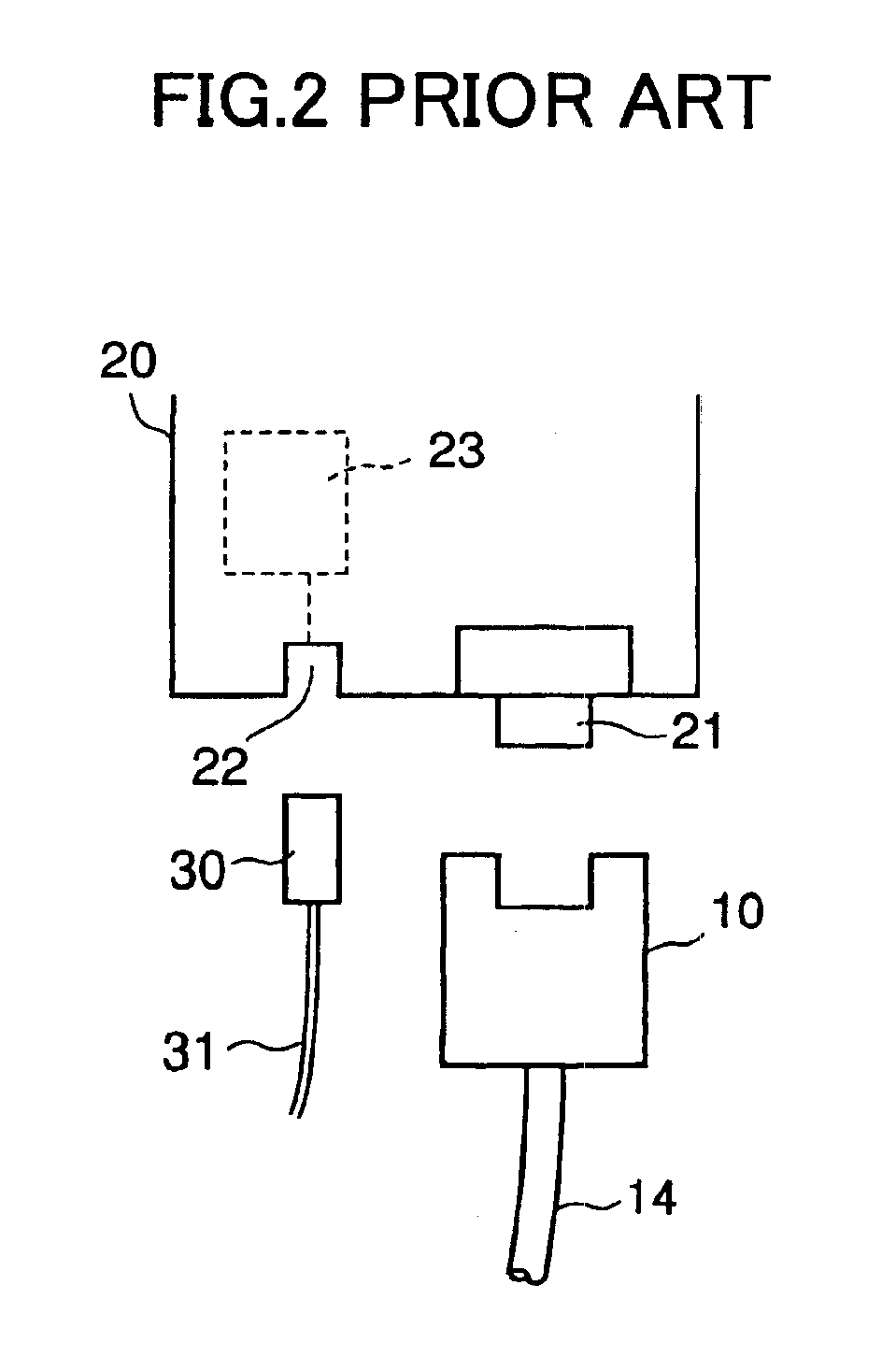
a technology of differential transmission and connectors, applied in the direction of electrical discharge lamps, coupling device connections, electric discharge tubes, etc., can solve the problems of user-intensive server apparatuses b>20/b>, and achieve the effect of reducing production costs

Inactive Publication Date: 2005-05-03
FUJITSU COMPONENENT LTD
View PDF6 Cites 22 Cited by
  • Summary
  • Abstract
  • Description
  • Claims
  • Application Information

AI Technical Summary

Benefits of technology

[0011]Accordingly, it is a general object of the present invention to provide a connector for differential transmission in which the above-described disadvantage is eliminated.
[0012]A more specific object of the present invention is to provide a connector for differential transmission that allows server apparatuses to have simpler structures.
[0014]The above-described connector may be used, being electrically connected to a differential transmission connector, so that differential electrical signals may be converted into light signals and transmitted. The above-described connector allows an apparatus to dispense with an optical connector, so that the apparatus is reduced in production cost.
[0016]The above-described connector may be used, being electrically connected to a differential transmission connector, so that differential electrical signals may be converted into light signals and transmitted. The above-described connector allows an apparatus to dispense with an optical connector, so that the apparatus is reduced in production cost. Further, the above-described connector has a photoelectric conversion part mounted on a rigid printed circuit board. Accordingly, it is easy to incorporate the photoelectric conversion part in the connector and to electrically connect a connector main body and the photoelectric conversion part.

Problems solved by technology

In particular, the optical fiber connector 22 and the photoelectric conversion module 23 are unnecessary to users who use the server apparatus 20 at a location close to the computer, thus making the server apparatus 20 costly for the users.

Method used


Image

  • Differential transmission connector
  • Differential transmission connector
  • Differential transmission connector

Examples


first embodiment

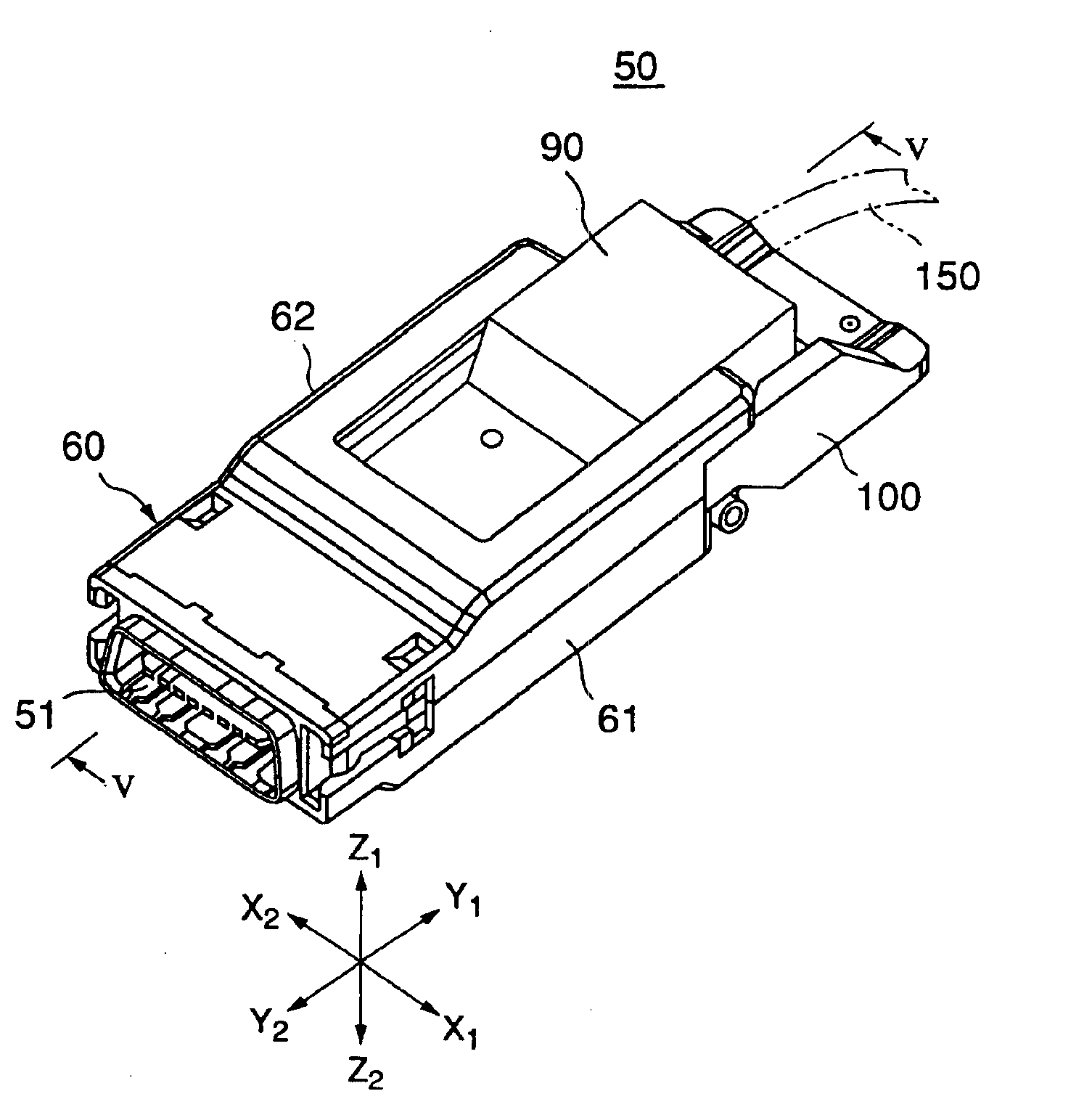
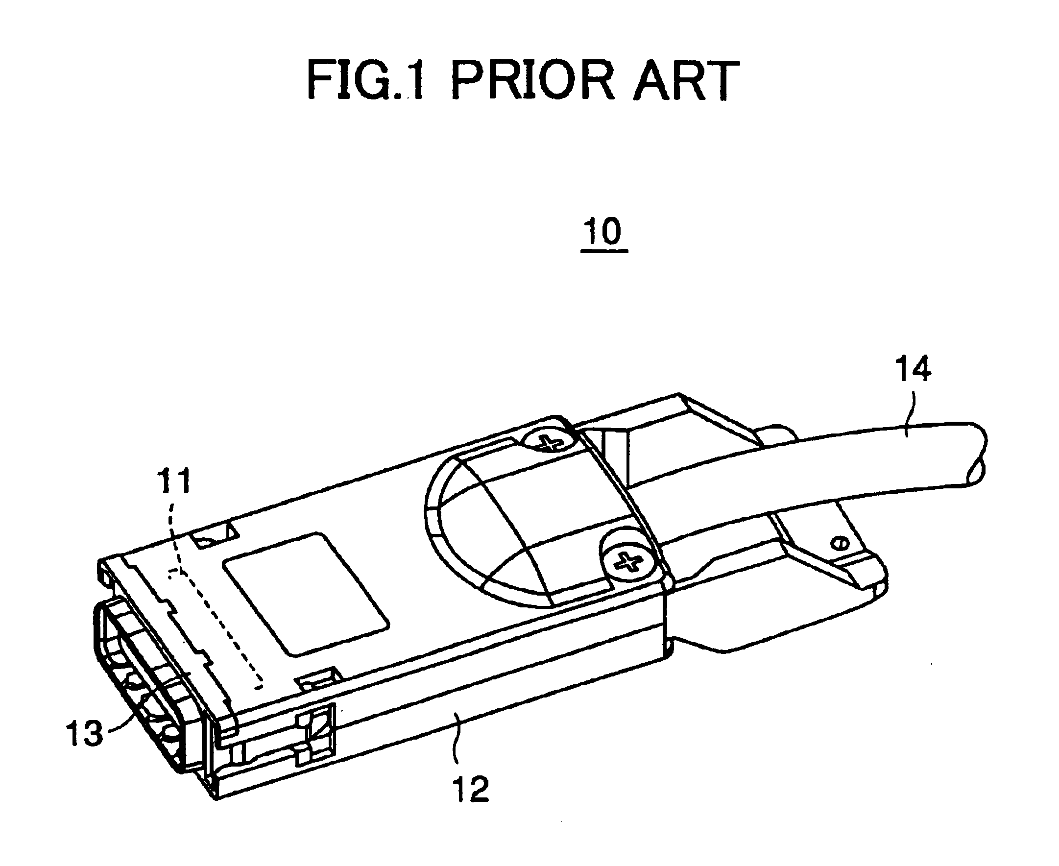
[0035]FIGS. 3, 4, and 5 are diagrams showing a cable-type plug connector for differential transmission 50 according to the present invention. In FIGS. 3, 4, and 5, the connector 50 is shown bottom side up for convenience of graphical representation. In the following description, the words “upper” and “lower” are used based on the positions of the connector 50 shown in the drawings. The connector 50 includes a housing 60, a differential transmission plug connector main body 70, and a photoelectric conversion module 90. The connector main body 70 and the module 90 are incorporated in the housing 60. The connector 50 is substantially equal in size, particularly, in height, to the conventional connector 10 of FIG. 1 (the connector 50 has a height h as shown in FIG. 5).

[0036]Referring to FIGS. 3 through 5, the connector 50 is configured so that the connector main body 70, a rigid printed circuit board 80, and the photoelectric conversion module 90 are incorporated in the housing 60 and a...

second embodiment

[0073]Further, the employment of the differential transmission plug connector main body 200 of a right-angle and surface-mounting type eliminates the necessity of connecting flexible cables to a connector and bending the flexible cables so that the flexible cables form a predetermined transmission path. Accordingly, it is easy to produce the connector 50A.

[0074]By replacing the differential transmission plug connector main body 70 or 200 with a differential transmission jack connector main body, a differential transmission jack connector including the differential transmission jack connector main body and the photoelectric conversion module 90 may be formed.


PUM


Abstract

A connector for differential transmission is disclosed. The connector includes a connector housing, a connector main body attached thereto, and a photoelectric conversion module provided to the connector housing to be electrically connected to the connector main body. The connector main body includes a differential transmission electric connector part connectable to the connector of an apparatus. Ground contact members and signal contact pairs each including first and second signal contact members are arranged alternately in the connector main body. The photoelectric conversion module includes a photoelectric conversion part and an optical fiber cable connector part to which an optical fiber cable is connectable. The differential transmission electric connector part and the optical fiber cable connector part are provided to the opposite ends of the connector housing.

Description

BACKGROUND OF THE INVENTION[0001]1. Field of the Invention[0002]The present invention relates generally to connectors for differential transmission, and more particularly to a connector for differential transmission employed for connection to computer apparatuses.[0003]2. Description of the Related Art[0004]Differential transmission has been employed in many cases as a method of transmitting data between personal computers and peripheral devices. Differential transmission uses a pair of lines for each data element, and simultaneously transmits a “+” signal to be transmitted and a “−” signal equal in magnitude and opposite in direction to the “+” signal. Differential transmission has the advantage of being less susceptible to noise compared with a normal transmission method.[0005]When the distance between a server apparatus and a computer apparatus is short, the server apparatus and the computer apparatus may be connected satisfactorily with an electric wire cable. However, if the se...

Claims


Application Information

Patent Timeline
Patent Type & Authority Patents(United States)
IPC IPC(8): H01R33/00H01R33/945H01R31/06H01R13/46G02B6/42
CPCH01R33/945H01R31/065H01R2201/06
Inventor ITO, TAKESHIKOBAYASHI, MITSURUMIYAZAWA, HIDEOSHIMIZU, NOBORU
Owner FUJITSU COMPONENENT LTD
Learn More