Control program for a device for photorefractive corneal surgery of the eye

a control program and corneal surgery technology, applied in the field of control program for the device for photorefractive corneal surgery of the eye, can solve the problems of eye optical imaging impairment not, lower-order visual disorders, and higher-order image defects

Inactive Publication Date: 2005-05-03
WAVELIGHT LASER TECH
View PDF11 Cites 65 Cited by
  • Summary
  • Abstract
  • Description
  • Claims
  • Application Information

AI Technical Summary

Benefits of technology

[0020]The invention correspondingly provides a method of generating a control program of the generic type mentioned in the introduction, in which, when generating the control program, the effect of the angle between the laser beam and the corneal surface on the energy density of the laser-beam spot incident on the corneal surface is taken into account.

Problems solved by technology

A particular problem in photorefractive keratectomy and LASIK involves the relative positioning of the laser beam and the eye.
However, the optical imaging in the eye is impaired not only by the said lower-order visual disorders, but also by so-called higher-order image defects.
Such higher-order image defects occur, in particular, after operative interventions on the cornea and inside the eye (cataract operations).
If there is an aberration, however, then individual displacements of each pattern point occur, because each individual beam passes through a particular corneal or pupillary area and experiences a deviation from the ideal path according to the non-uniform optical effect.
And, if this device produced significant improvements compared with the previous solutions, it was found that the treatment successes in some cases were not as good as might have been expected in view of the accuracy with which the photoablation profile had been compiled.

Method used


Image

  • Control program for a device for photorefractive corneal surgery of the eye
  • Control program for a device for photorefractive corneal surgery of the eye
  • Control program for a device for photorefractive corneal surgery of the eye

Examples


Embodiment Construction

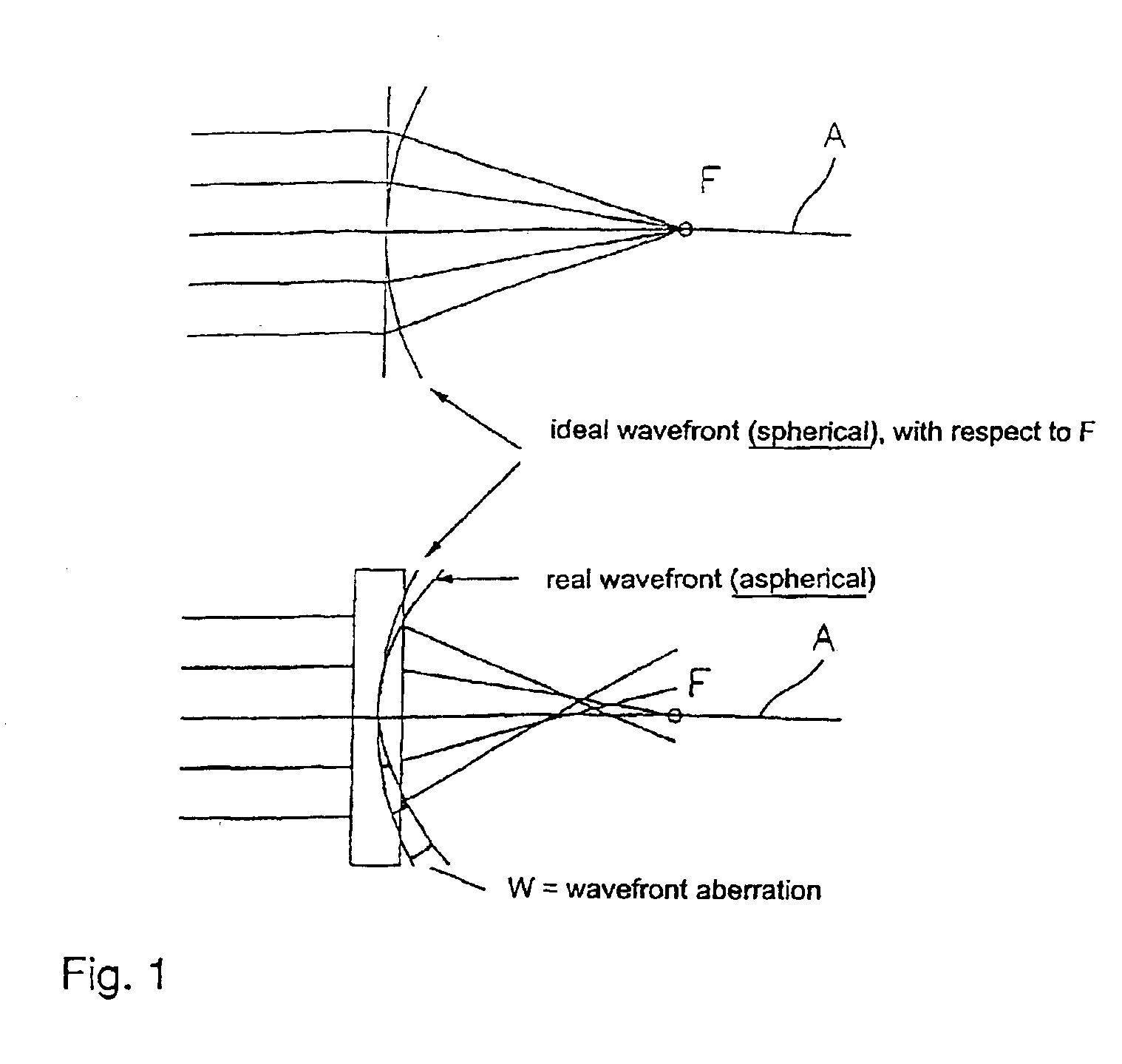
[0042]FIG. 1 schematically shows the aforementioned wavefront aberration of an eye, i.e. the deviation of the real, aspherical wavefront from the ideal wavefront. A is the optical axis of the system and F is the focal point, which is also the imaginary starting point of the radiation in the case of an ideal wavefront.

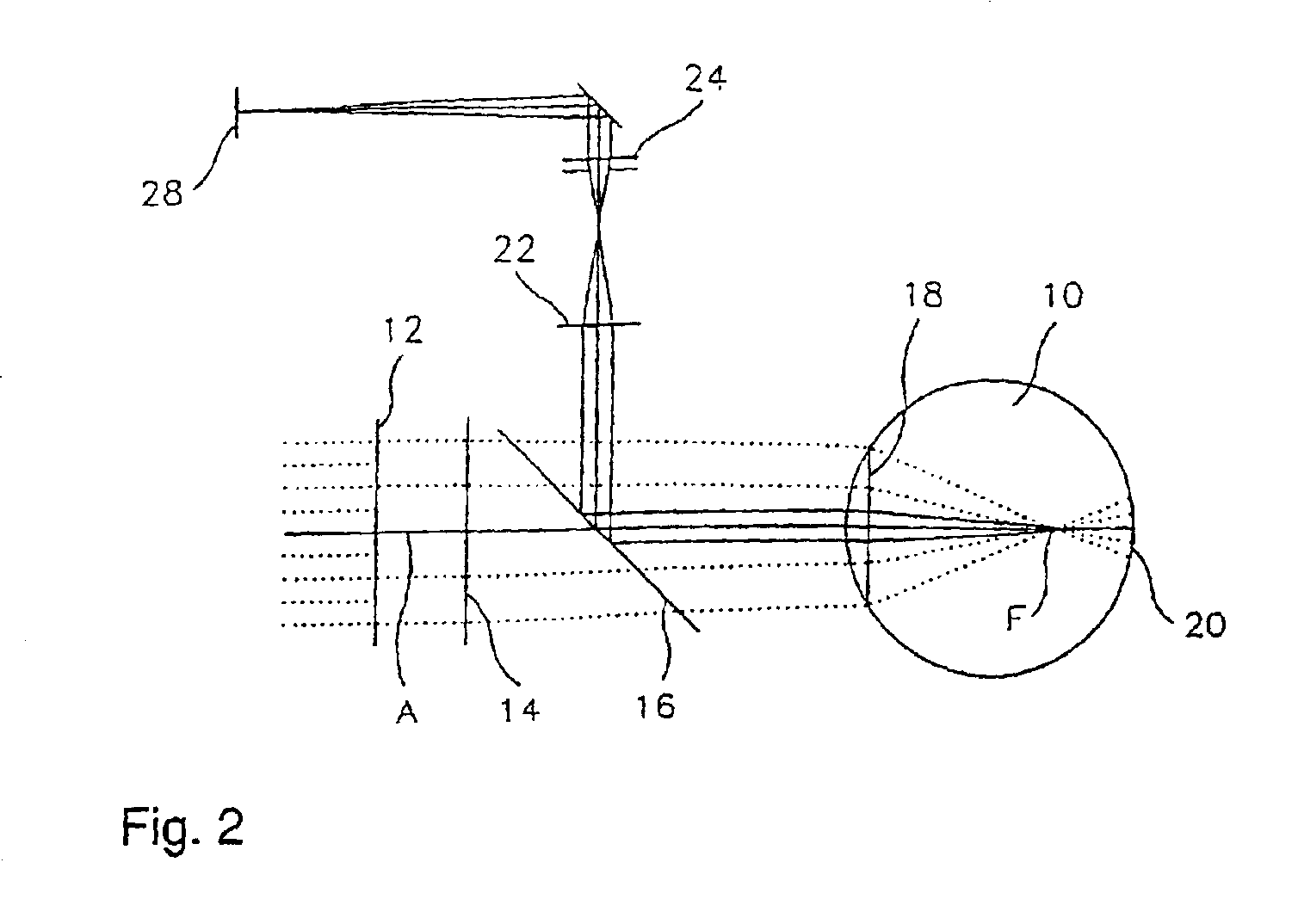
[0043]FIG. 2 schematically shows the optical layout of a video aberroscope for measuring the wavefront aberration of an eye 10. The green light from a HeNe laser (543 nm) is broadened to a diameter of approximately 12 mm and subsequently split by means of a hole mask 12, in which a plurality of equidistant holes are formed, into a corresponding number of parallel individual beams. According to FIG. 2, these individual beams, which are indicated only schematically by dotted lines, run parallel to the optical axis A of the system. Using an aberroscope lens 14 (converging lens) in front of the eye 10, these beams are refracted in such a way that they are focused at a parti...


PUM


Abstract

In a control program, according to which a laser-beam spot is guided, while being controlled with respect to position and time, over a cornea to be corrected photorefractively, so as to ablate a predetermined ablation profile therefrom, the effect of the angle between the laser earn and the corneal surface on the energy density of the laser-beam spot incident on the corneal surface and/or on the fraction of the laser-beam energy incident on the corneal surface which is reflected away, is taken into account when generating the control program.

Description

BACKGROUND OF THE INVENTION[0001]The invention relates to a control program, according to which a laser-beam spot is guided, while being controlled with respect to position and time, over a cornea to be corrected, so as to ablate a predetermined ablation profile therefrom. The invention also relates to an electronic computer and to a device for corneal surgery of the eye, in which a control program generated by means of the method is used.[0002]Photorefractive keratectomy has become a widely established method of correcting lower-order visual disorder, for example myopia, hyperopia, astigmatism, myopic astigmatism and hyperopic astigmatism. The term “photorefractive keratectomy (PRK)” is usually understood as meaning only intervention on the corneal surface, after the so-called corneal epithelium has been removed. After the epithelium is removed, the Bowman's membrane, or corneal stroma, is exposed and can be ablated using a laser. Distinction is generally made between PRK and the L...

Claims


Application Information

Patent Timeline
Patent Type & Authority Patents(United States)
IPC IPC(8): A61F9/007A61F9/013A61F9/01
CPCA61F9/00806A61F9/013A61F9/00817A61F2009/00887A61F2009/00853A61F2009/00872A61F2009/00848
Inventor MROCHEN, MICHAELKAEMMERER, MAIKSEILER, THEO
Owner WAVELIGHT LASER TECH
Why Eureka
Try Eureka