Split ring bone screw for a spinal fixation system

a bone screw and split ring technology, applied in the field of spinal implant systems, can solve the problems of limited positioning, undue stress further affecting adjoining bones, and the component design and bone screw design inhibit the application to a particular spinal injury, and achieve the effect of satisfying correction

Inactive Publication Date: 2005-05-03
MULLANE THOMAS
View PDF27 Cites 184 Cited by
  • Summary
  • Abstract
  • Description
  • Claims
  • Application Information

AI Technical Summary

Benefits of technology

[0039]Thus, it is an objective of the present invention to provide a bone screw assembly for a spinal fixation system that permits component adjustment during installation, thereby enabling satisfactory correction of a wide variety of spinal deformities.
[0040]It is an additional objective of the present invention to provide a bone screw assembly that includes a split ring locking mechanism that is simple and reliable. The split ring has a tapered aperture and a spherical outer surface to mate with the tapered end of a toggle bolt.
[0041]It is a further objective of the present invention to provide a spinal fixation system that includes two-piece connectors that may be mounted along, and removed from, a support rod without requiring movement of adjacent connectors.
[0042]It is yet another objective of the present invention to provide a spinal fixation system that includes mounting hardware which requires a minimum number of tools.
[0043]It is also an objective of the present invention to provide a spinal fixation system that allows modular replacement of damaged components.

Problems solved by technology

Unfortunately, known spinal implant systems often correct one set of problems only to create new ones.
While bone screws are commonly used for anchoring, they are limited in their positioning due to the design of component pieces.
In many instances the combination of existing component design and bone screw design inhibits application to a particular spinal injury.
Perpendicular placement of a bone screw therein may not be possible and placement at an angle thereto may cause undue stress further affecting adjoining bones.
A problem with specially designed clamps is that bone structure cannot be determined until the patient's bone is exposed causing the necessity of a large inventory of various sized clamps to be on hand during surgery, of which the surgeon must search to find the right combination.
Even if a clamp combination is predicted, insertion of the screw may still require angular insertion due to muscle or tender nerve locations.
The result is a bone screw which exerts unpredictable forces upon attachment to component connectors.
Further, any movement of muscle and other tissue increases the difficulty of the operation and can be a major trauma to a person.
A problem with the screw is the need for the locking pin and the inability of the base screw to accommodate a threaded extension bolt.
Unfortunately, although these so-called “rigid screw” fixation systems can alter the curvature of a patient's spine, they can also be difficult to install.
As a result, the number of suitable anchoring locations is limited.
Achieving a proper fit between all of the components while contending with the constraints encountered during surgery is often difficult.
In severe cases, a suitable fit may not be achieved and the surgery will be unsuccessful.
Additionally, the nature of the installation process required for rigid screw fixation systems often subjects the system components to pre-loading that unduly stresses the interface between the patient's bone and the employed anchoring screws.
Corrective surgery to reattach anchoring screws exposes an already-weakened region to additional trauma and presents the risk of additional damage.
Unfortunately, some adjustable fixation systems tolerate only limited amounts of relative adjustment between components, operating best when loaded in one of several preferred arrangements.
Additionally, many adjustable fixation systems are prone to post-surgery component loosening.
As a patient moves about during day-to-day living, his spine is subjected to a seemingly-endless amount of dynamic loading.
Almost all activity requires some form of back motion; over time, this cyclic movement tends to work the components of many adjustable fixation systems loose.
Although capable of being locked in place, these systems are often difficult to secure, requiring an excess of tools during the installation process.
The need for extra tools, such as those required to shave or crimp key portions of a fixation system, increasing surgical risk by adding complexity and increasing the number of required steps.
Although locking-component fixation systems exist, many of them unduly increase the dangers of back implant surgery to an unacceptable level.
Additionally, many spinal fixation systems do not permit component repairs.
Often, such removal produces an undesirable “domino-effect,” requiring that several connectors be slid off to allow removal of the damaged connector.
Such requirements add unnecessary difficulty to an already-complex procedure.

Method used


Image

  • Split ring bone screw for a spinal fixation system
  • Split ring bone screw for a spinal fixation system
  • Split ring bone screw for a spinal fixation system

Examples


Embodiment Construction

[0050]It is to be understood that while a certain form of the invention is illustrated, it is not to be limited to the specific form or arrangement of parts herein described and shown. It will be apparent to those skilled in the art that various changes may be made without departing from the scope of the invention and the invention is not to be considered limited to what is shown in the drawings and described in the specification.

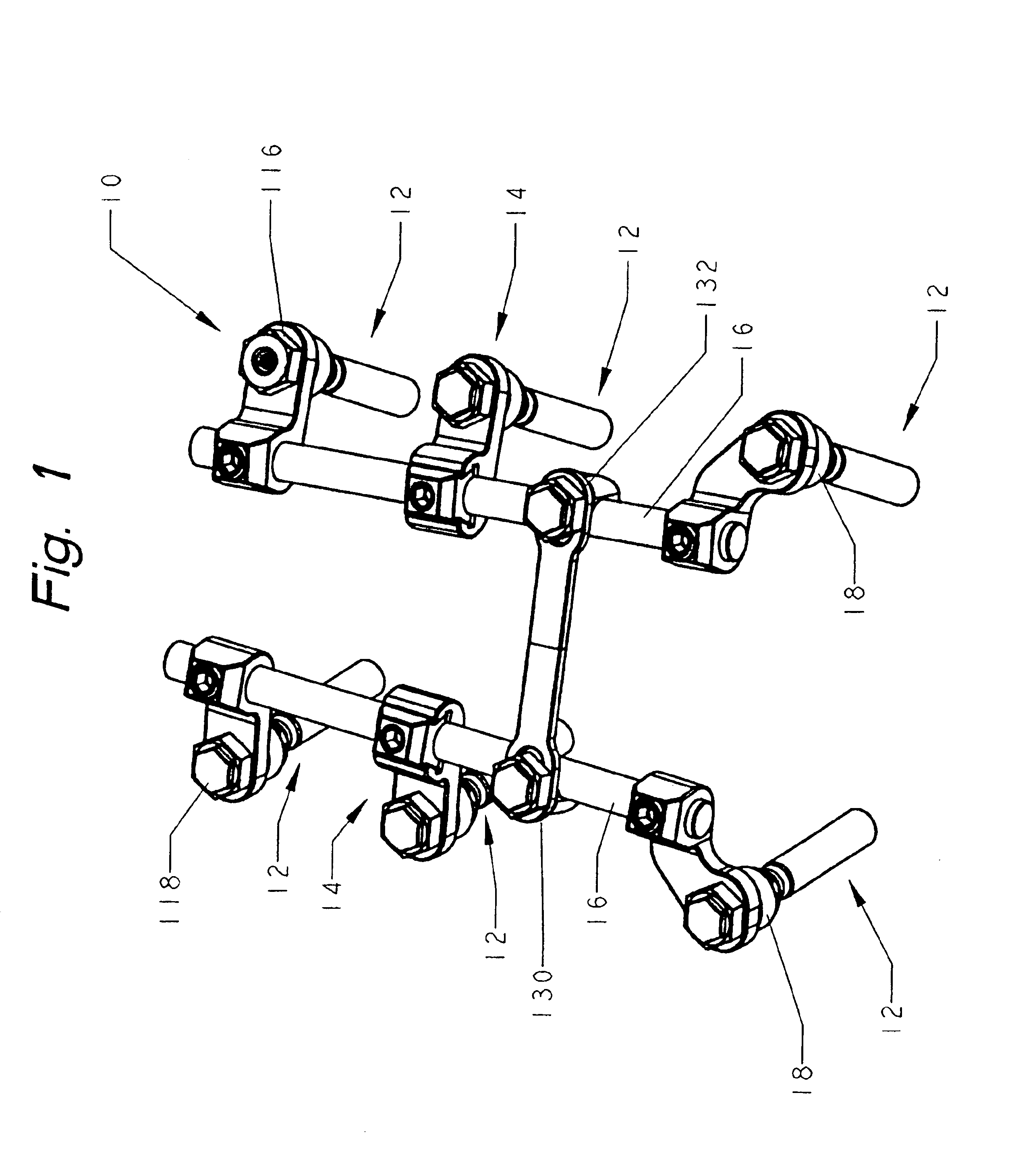
[0051]Now with reference to FIG. 1, the spinal fixation system 10 of the present invention is shown. By way of overview, the Fixation System 10 includes a collection of bone-engaging anchoring assemblies 12 that are joined via connectors 14,14′ to stabilizing rods 16, 16′. The specifics of the spinal fixation system 10 will now be discussed in more detail.

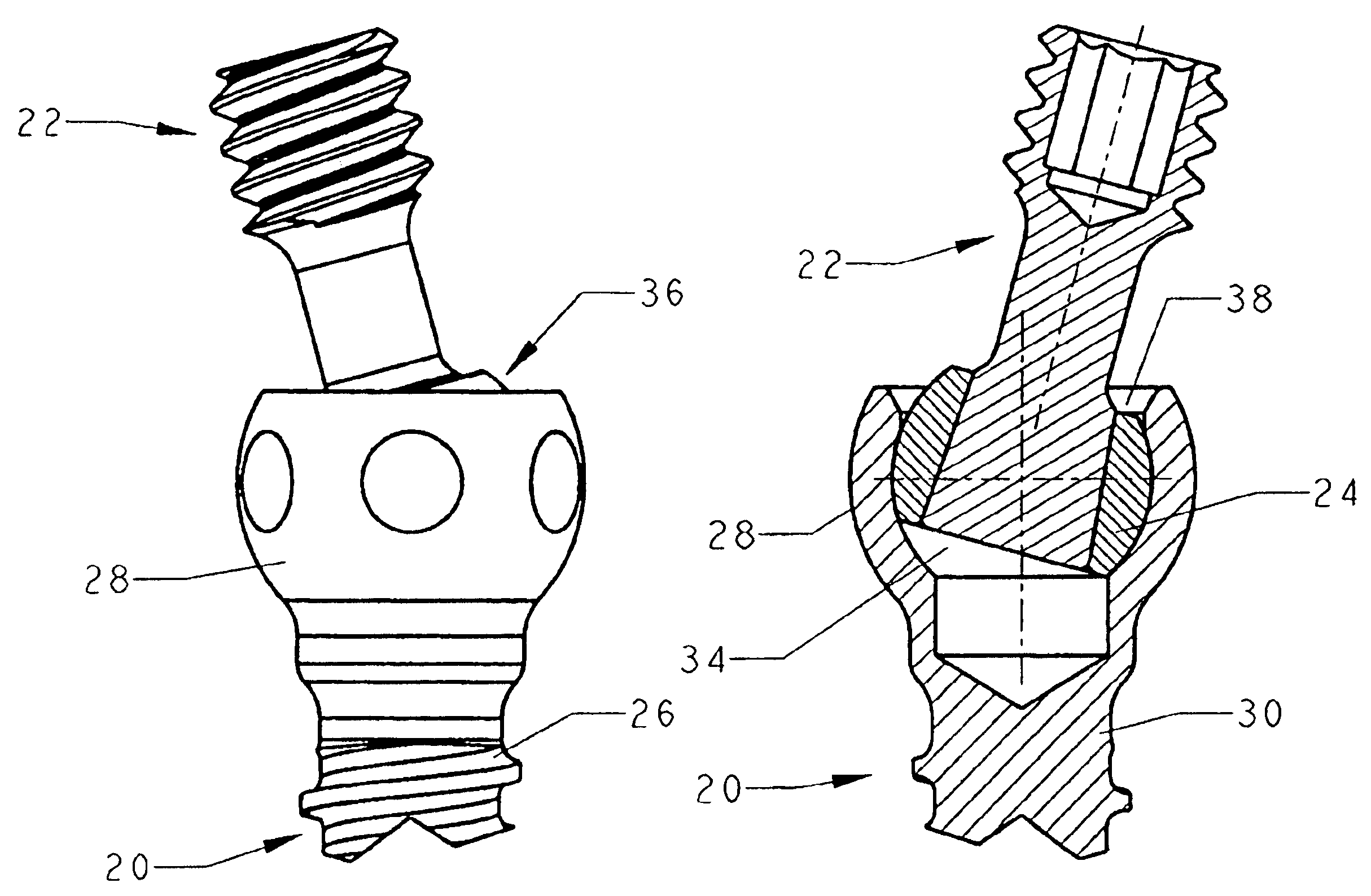
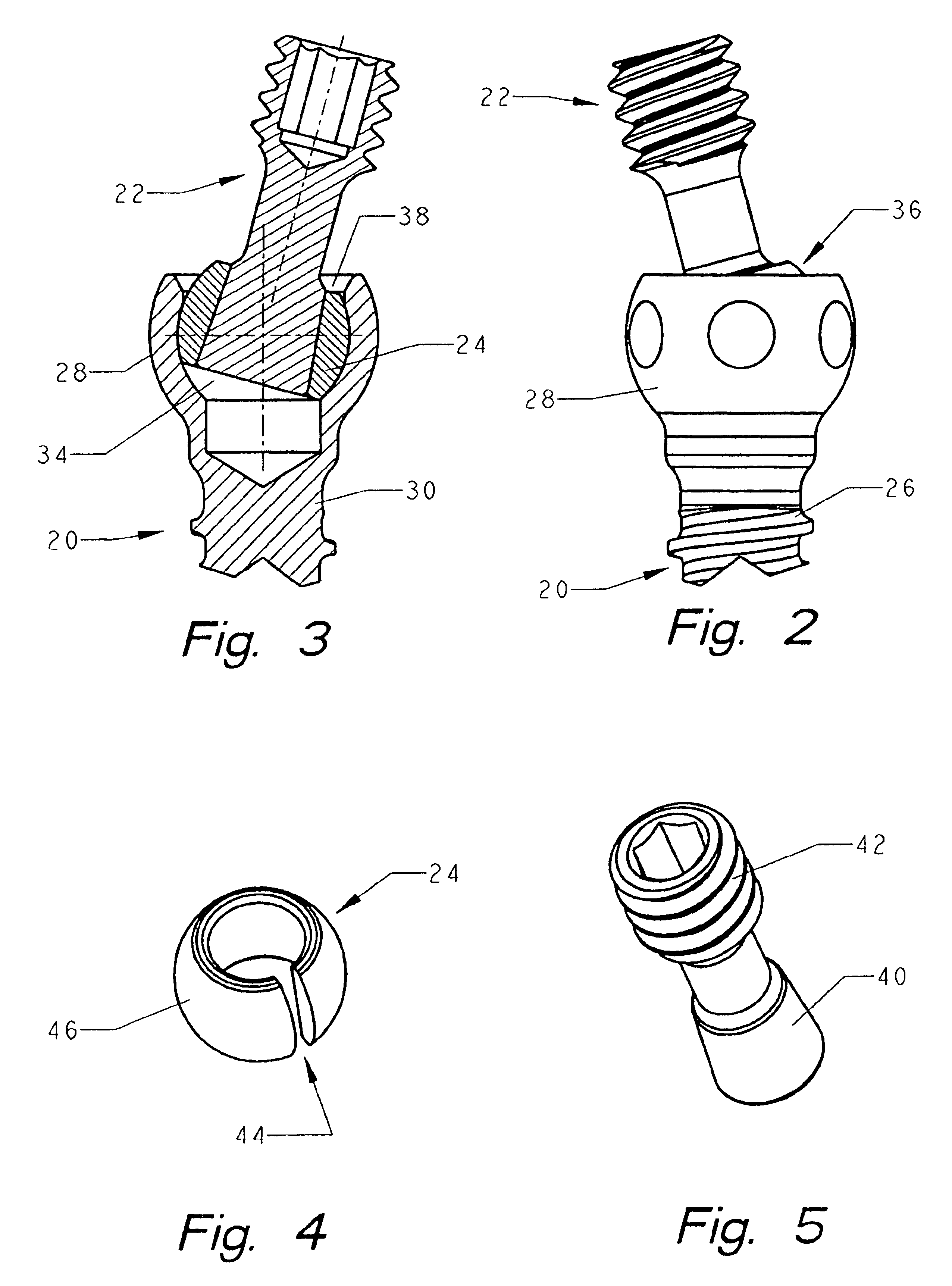
[0052]With additional reference to FIG. 2, one of the included anchoring assemblies 12 is shown in an assembled state. Each anchoring assembly 12 also includes a pedicle screw 20, a toggle bolt 22, and a s...


PUM


Abstract

An adjustable spinal fixation system is composed of a collection of anchoring assemblies attached, via a variety of connectors, to spine-stabilizing rods. The anchoring assemblies include a linking member attached in a ball-and-socket fashion to a bone-engaging member that is adapted to engage a spinal bone of a patient. The linking member joins one of the included connectors to an associated bone-engaging member. The connectors are selectively attached to one of the stabilizing rods. The anchoring assemblies each include a support collar and a split retention ring that cooperate to allow adjustment of the bone-engaging member and corresponding connector during surgery. When surgery is complete, a securing nut and locking bolt cooperate with the support collar and split retention ring to maintain the relative position of the entire fixation system, preventing unwanted movement between the system components.

Description

[0001]This application is a continuation in part of application Ser. No. 09 / 981,961, filed Oct. 17, 2001 now U.S. Pat. No. 6,623,485.FIELD OF THE INVENTION[0002]This invention is directed to spinal implant systems and, in particular, to a multi-component adjustable implant system capable of maintaining a desired spacial relationship among the bones of a patient's spine.BACKGROUND OF THE INVENTION[0003]This application provides improvements to the articulating toggle bolt bone screw disclosed in U.S. Pat. No. 5,628,740, issued to Mullane on May 13, 1997 and U.S. Pat. No. 6,050,997 issued to Mullane on Apr. 18, 2000. The contents of those patents are hereby incorporated by reference.[0004]For individuals with spinal pathologies, the development of spinal fixation devices represents a major medical breakthrough. Surgically implanted fixation systems are commonly used to correct a variety of back structure problems, including those which occur as a result of trauma or improper developme...

Claims


Application Information

Patent Timeline
Patent Type & Authority Patents(United States)
IPC IPC(8): A61B17/70
CPCA61B17/7035A61B17/7041A61B17/7049
Inventor DOUBLER, ROBERT L.HAMMILL, JOHN E.
Owner MULLANE THOMAS
Why Eureka
Try Eureka