
Diesel particulate filter apparatus

a filter apparatus and diesel technology, applied in the direction of filtration separation, auxiliary pretreatment, separation processes, etc., can solve the problems of complex structure design, reduced total opening area, and increased gas-flow resistance, so as to increase the gas-flow resistance without increasing the length of the diffusion chamber

Inactive Publication Date: 2005-05-03
CALSONIC KANSEI CORP
View PDF17 Cites 24 Cited by
  • Summary
  • Abstract
  • Description
  • Claims
  • Application Information

AI Technical Summary

Benefits of technology

[0017]The invention has been conducted in order to solve the problems of the conventional art. It is an object of the invention to provide a diesel particulate filter apparatus (DPF apparatus) in which exhaust gas is enabled to uniformly flow through a diesel particulate filter (DPF) without increasing the length of a diffusion chamber and raising the gas-flow resistance.

Problems solved by technology

In the configuration where only the perforated plate 108 is employed, because that the amount of exhaust gas of the engine largely changes, there is a problem that in order to equalize the flow rate profile over the whole area (uniformalize the gas flow also in a peripheral portion), the total opening area must be reduced to raise the gas-flow resistance.
However, such a structure requires a complicated design, and hence cannot be practically used.

Method used


Image

  • Diesel particulate filter apparatus
  • Diesel particulate filter apparatus
  • Diesel particulate filter apparatus

Examples


first embodiment

[First Embodiment]

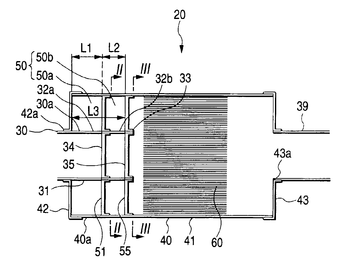
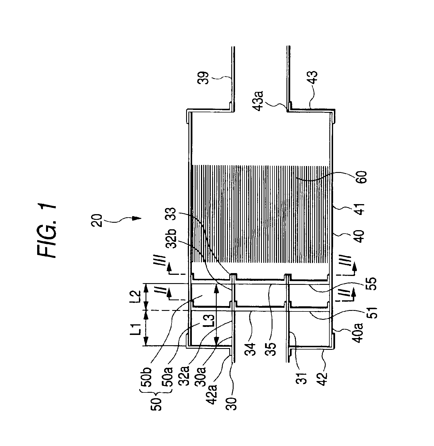
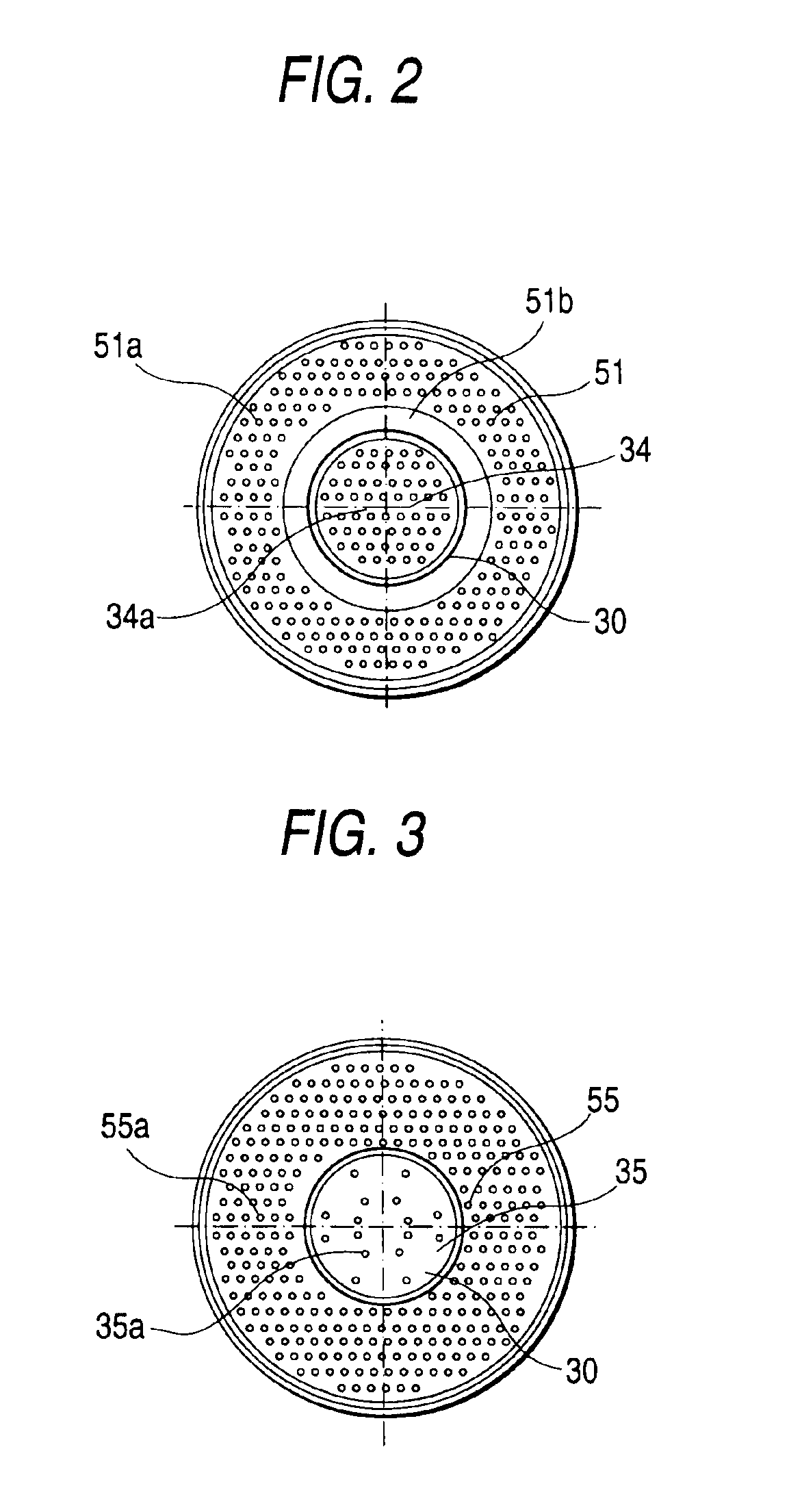
[0036]FIGS. 1 to 5 show a diesel particulate filter apparatus 20 (hereinafter referred to as “DPF apparatus 20”) of a first embodiment of the invention.

[0037]The DPF apparatus 20 of the first embodiment includes a container 40 formed in tube-like shape having rectangle section, an exhaust gas inlet pipe 30 inserted on the upstream side, an exhaust gas outlet pipe 39 disposed on the downstream side, a diffusion chamber 50 disposed on the upstream side in the container 40 and along the exhaust gas inlet pipe 30, a diesel particulate filter 60 (hereinafter referred to as “DPF 60”) made of ceramics and disposed in the container 40 downstream of the diffusion chamber 50.

[0038]In the diffusion chamber 50, a plurality of openings 32a and 32b are opened in a wall 31 of the exhaust gas inlet pipe 30.

[0039]Two perforated plugs 34 and 35 are separately disposed inside an end portion 33 of the exhaust gas inlet pipe 30. The total opening area of openings 34a formed in the perf...

second embodiment

[Second Embodiment]

[0098]FIG. 8 shows a second embodiment of the invention.

[0099]The second embodiment is different from the first embodiment in that the partition plate 51 is omitted, but the plate 51b remains to be used.

[0100]In the second embodiment, an opening 53 is formed between the plate 51b and the shell 41 of the container 40, and the total opening area of the opening 53 is larger than that of the openings 55a formed in the partition plate 55 on the downstream side.

[0101]Therefore, the second embodiment can attain the same effects as those of the first embodiment.

third embodiment

[Third Embodiment]

[0102]FIG. 9 shows a third embodiment of the invention.

[0103]The embodiment is different from the first embodiment in that reinforcement beads 51b and 55b are formed on the partition plates 51 and 55, respectively.

[0104]According to the third embodiment, the mechanical strength such as rigidity of the partition plates 51 and 55 can be enhanced.


PUM

PropertyMeasurementUnit
Areaaaaaaaaaaa

Abstract

A DPF apparatus includes: a container; an exhaust inlet pipe; a diesel particulate filter; a pair of perforated plugs; a pair of partition plates; and a diffusion chamber. The exhaust inlet pipe is inserted into the container and having openings formed in a pipe wall thereof. The diesel particulate filter is disposed inside the container. The perforated plugs are separately disposed inside an end portion of the exhaust inlet pipe. The partition plates have one or more openings and disposed on the pipe wall of the exhaust inlet pipe. The diffusion chamber is defined by an inner wall face of the container, the perforated plugs, the partition plates, and the pipe wall of the exhaust inlet pipe.

Description

[0001]The present disclosure relates to the subject matter contained in Japanese Patent Application No. 2002-091293 filed on Mar. 28, 2002, which is incorporated herein by reference in its entirety.BACKGROUND OF THE INVENTION[0002]1. Field of the Invention[0003]The present invention relates to a diesel particulate filter apparatus.[0004]2. Description of the Related Art[0005]Conventionally, as a diesel particulate filter apparatus (hereinafter referred to as “DPF apparatus”), there is an apparatus in which a diesel particulate filter (hereinafter referred to as “DPF”) made of ceramics is held in a container to which an exhaust gas inlet pipe connected to an exhaust gas passage of a diesel engine, and an exhaust gas outlet pipe connected to the downstream side are attached. Exhaust gas which flows into the apparatus through the exhaust gas inlet pipe is passed through a DPF, and is then discharged from the exhaust gas outlet pipe on the downstream side. In such an apparatus, the cont...

Claims


Application Information

Patent Timeline
IPC IPC(8): F01N3/021F01N3/02
CPCF01N3/021F01N2240/20F01N2240/26F01N2260/14Y10S55/30F01N2470/08F01N2490/00Y02T10/20F01N2470/02Y02T10/12
Inventor KANEMATSU, OSAMU
Owner CALSONIC KANSEI CORP
Learn More