
Electro drive

a technology of electro-driven drives and bearings, which is applied in the direction of supporting/enclosing/casings, mechanical energy handling, magnetic circuit shapes/forms/construction, etc., can solve the problems of lateral displacement of the rotor over its entire length, unstable support, and relatively expensive components of electro-driven components, etc., to achieve economic and compact construction, reduce the overall dimension, and reduce the air gap

Inactive Publication Date: 2005-05-03
JOHNSON ELECTRIC SA
View PDF20 Cites 10 Cited by
  • Summary
  • Abstract
  • Description
  • Claims
  • Application Information

AI Technical Summary

Benefits of technology

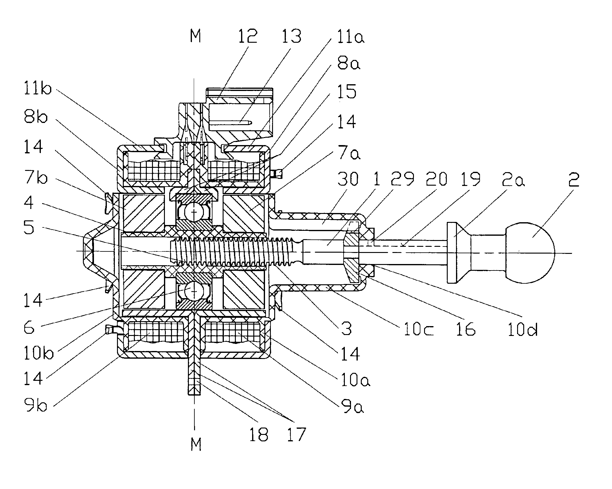
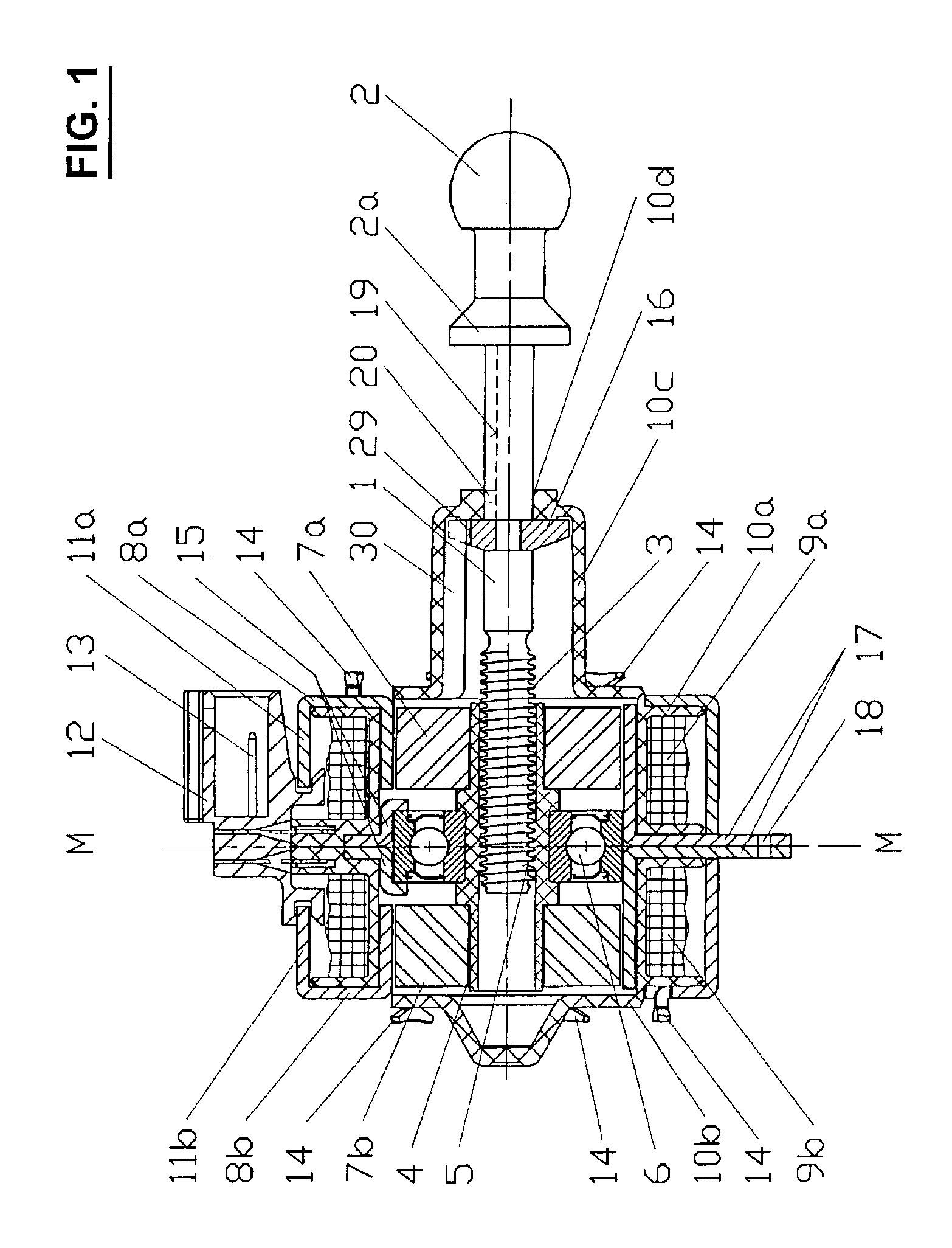
[0002]It is an object of the present invention to avoid the mentioned principal drawbacks and to provide an electro drive having an economical and compact construction. This object is achieved in that a rotor bearing is axially arranged within the axial length of the rotor. Thus, only one bearing assembly is required, and the effect of possible tilting movements of the rotor will only correspond to half the actual rotor length, thereby allowing a smaller air gap and thus smaller overall dimensions under otherwise identical conditions.

Problems solved by technology

This solution ensures a stable support of the rotor, but the two bearing assemblies are space-consuming, and the bearings, especially if they are ball-bearings, are a relatively expensive component of the electro drive.
It is also known to provide a bearing on one side of the rotor only, but this will result in an unstable support.
In particular, tilting movements due to bearing clearances of the rotor will lead to a lateral displacement of the rotor over its entire length.
Therefore, a relatively large air gap must be provided between the rotor and the stator in order to avoid contact between the rotor and the stator, thereby causing additional complications.
This in turn will lead to larger dimensions for the same power of the motor, and correspondingly to increased costs.

Method used


Image

  • Electro drive
  • Electro drive
  • Electro drive

Examples


Embodiment Construction

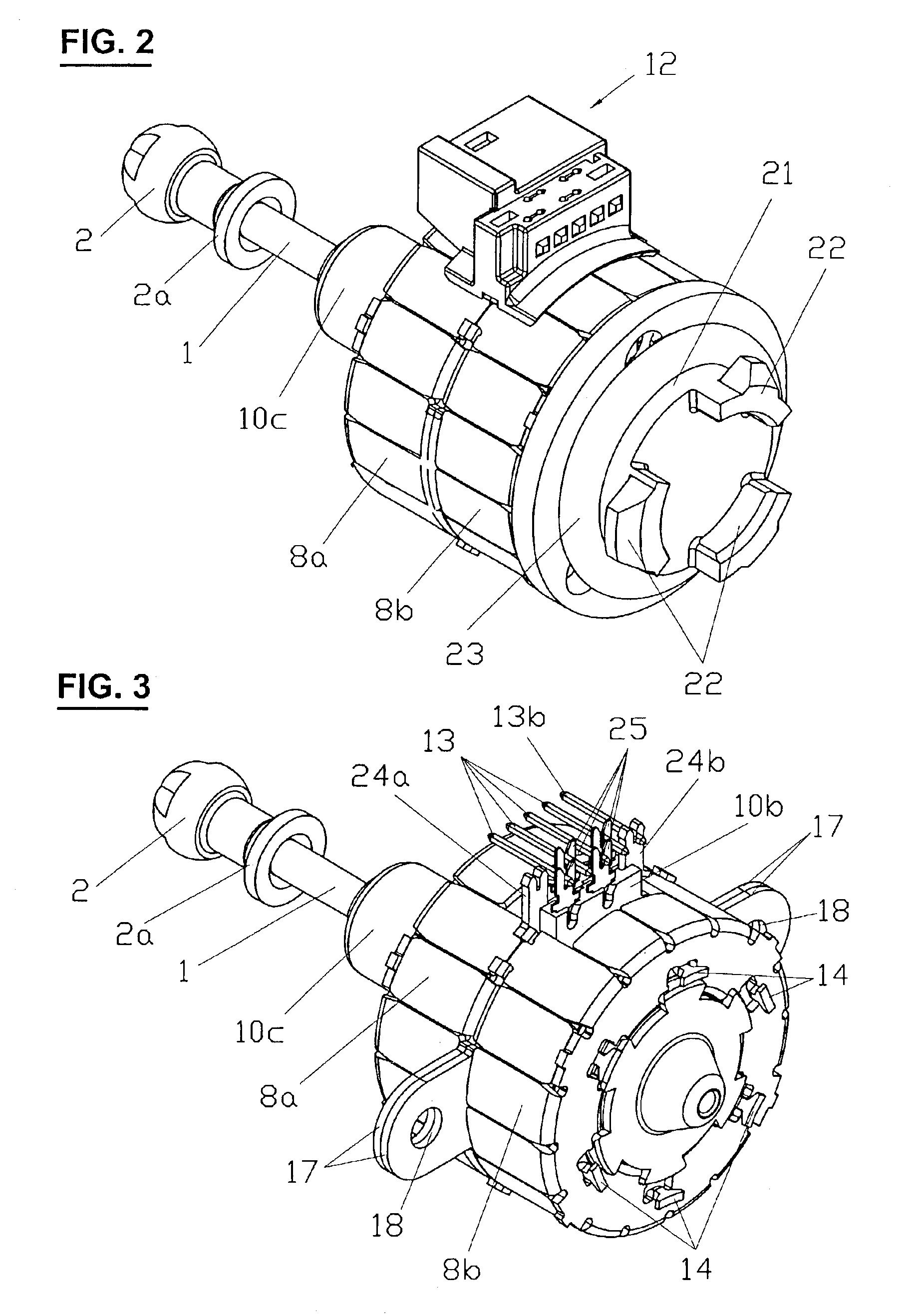
[0006]The linear motor drive shown in FIG. 1 is an electro drive comprising e.g. a stepper motor and may be used for actuating an adjustable member, e.g. the reflector of a vehicle lighting system. For this purpose the motor drive comprises an actuating rod 1 which is linearly moveable along its axis and whose head 2 may be coupled to the adjustable member. The end of actuating rod 1 opposite to head 2 is in the form of a screw 3 and engages in a sleeve 4 provided with an internal thread 5 at the center thereof.

[0007]Sleeve 4 is the hub of a rotor and is rotatably journalled by means of a ball bearing 6. On both sides of the ball bearing 6 and symmetrically thereto, two annular permanent magnets 7a resp. 7b of the same kind are mounted on hub 4. The stator of the motor drive comprises two axially offset portions 8a and 8b that are arranged essentially symmetrically to the center plane M of the motor drive.

[0008]The two stator portions 8a and 8b comprises each an inner and outer stat...


PUM


Abstract

The electro drive comprises a stator, a rotor, and a rotor bearing which is axially arranged within the axial length of the rotor.

Description

BACKGROUND OF THE INVENTION[0001]The present invention refers to an electro drive comprising a stator and a rotor. Generally, the rotor of such electro drives is journalled in two bearings arranged on each side of the rotor. This solution ensures a stable support of the rotor, but the two bearing assemblies are space-consuming, and the bearings, especially if they are ball-bearings, are a relatively expensive component of the electro drive. It is also known to provide a bearing on one side of the rotor only, but this will result in an unstable support. In particular, tilting movements due to bearing clearances of the rotor will lead to a lateral displacement of the rotor over its entire length. Therefore, a relatively large air gap must be provided between the rotor and the stator in order to avoid contact between the rotor and the stator, thereby causing additional complications. This in turn will lead to larger dimensions for the same power of the motor, and correspondingly to inc...

Claims


Application Information

Patent Timeline
Patent Type & Authority Patents(United States)
IPC IPC(8): H02K5/173H02K3/52H02K7/06H02K3/46H02K5/00H02K5/22H02K37/14H02K37/12
CPCH02K3/525H02K5/00H02K5/225H02K7/06H02K5/173H02K37/14H02K7/081H02K2201/12
Inventor WATZEK, MICHAELBOETTGER, AXELRIEDO, DANIEL
Owner JOHNSON ELECTRIC SA
Learn More