Tire pressure monitoring auto location assembly

a technology for auto location and tire pressure, applied in the direction of electric signalling details, instruments, transportation and packaging, etc., can solve the problems of increasing susceptibility to puncture, negatively affecting performance, and affecting performance, so as to reduce effort and error, the effect of reducing cost and weigh

Inactive Publication Date: 2005-05-03
SENSATA TECHNOLOGIES INC
View PDF19 Cites 54 Cited by
  • Summary
  • Abstract
  • Description
  • Claims
  • Application Information

AI Technical Summary

Benefits of technology

[0007]It is therefore an object to the present invention to provide an automotive tire pressure monitoring assembly with reduced effort and error. It is further object to the present invention to provide an automotive tire pressure monitoring assembly with reduced cost and weight properties.

Problems solved by technology

Although present vehicles often include new and increasingly complex components, many traditional components remain as crucial parameters in the vehicles operation.
Excess tire pressure can negatively impact performance and may increase susceptibility to puncture.
Low tire pressure can negatively impact performance, increase wear, and may generate excess heat.
It is known that tires often lose air pressure during operation of the vehicle.
Tire pressure is often lost gradually, making the point at which inflation pressure drops below the desired pressure range difficult to detect.
Manually operated tire pressure gauges are often unreliable and inaccurate.
Furthermore, the time and effort required for consumers to actively monitor their tire pressure using such manually operated gauges often renders them unused.
In-vehicle tire-pressure monitoring systems often present considerable design challenges to automotive designers.
These systems, however, are susceptible to commonplace automotive maintenance procedures such as tire rotation and replacement.
This methodology requires undesirable customer effort and may be prone to errors.
Automated learning interfaces eliminate both effort and error factors, but presently do so at the expense of undesirably added cost and weight.
This is an expensive solution and adds additional weight to the vehicle by positioning a transmitter in each wheel well.

Method used


Image

  • Tire pressure monitoring auto location assembly
  • Tire pressure monitoring auto location assembly

Examples


Embodiment Construction

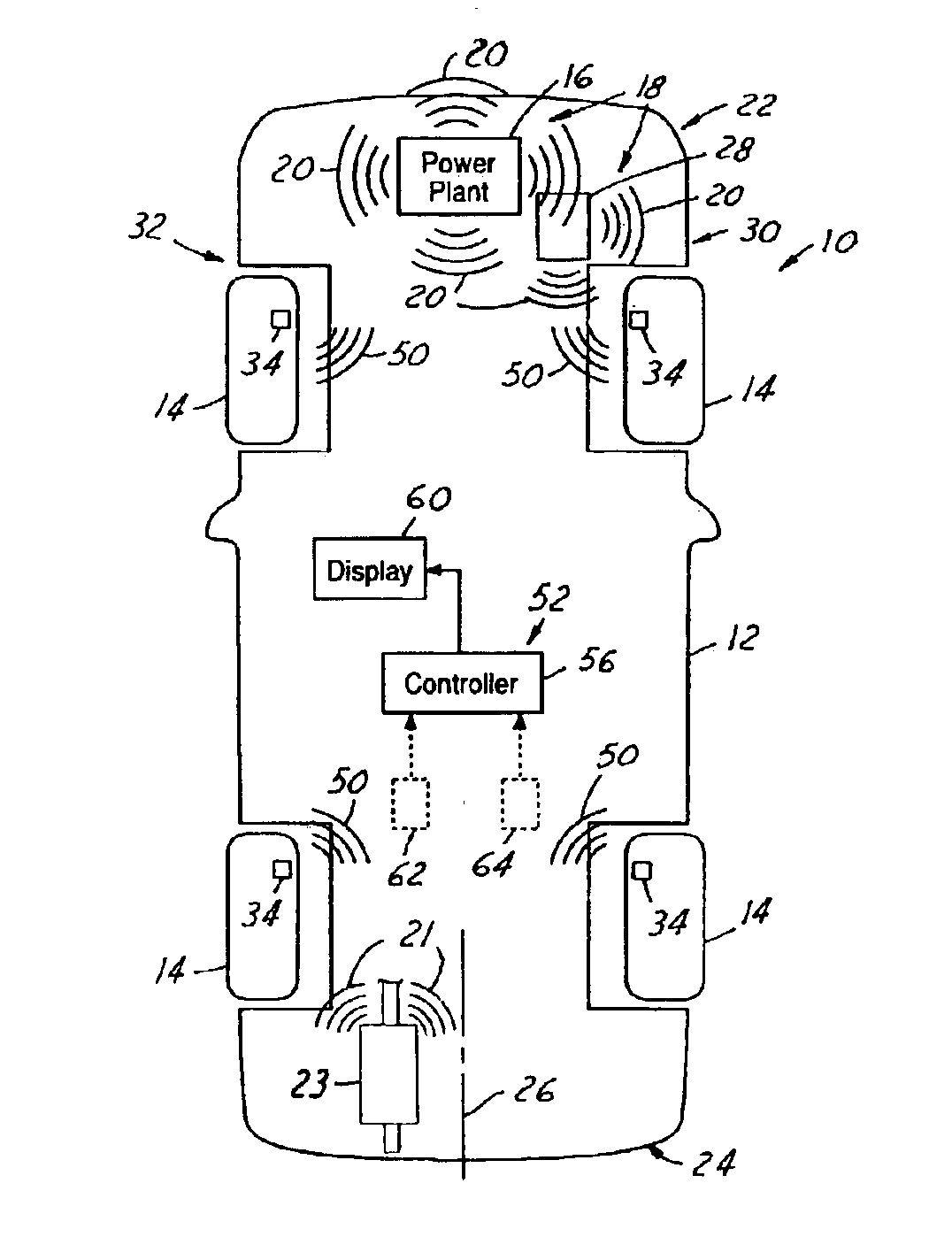
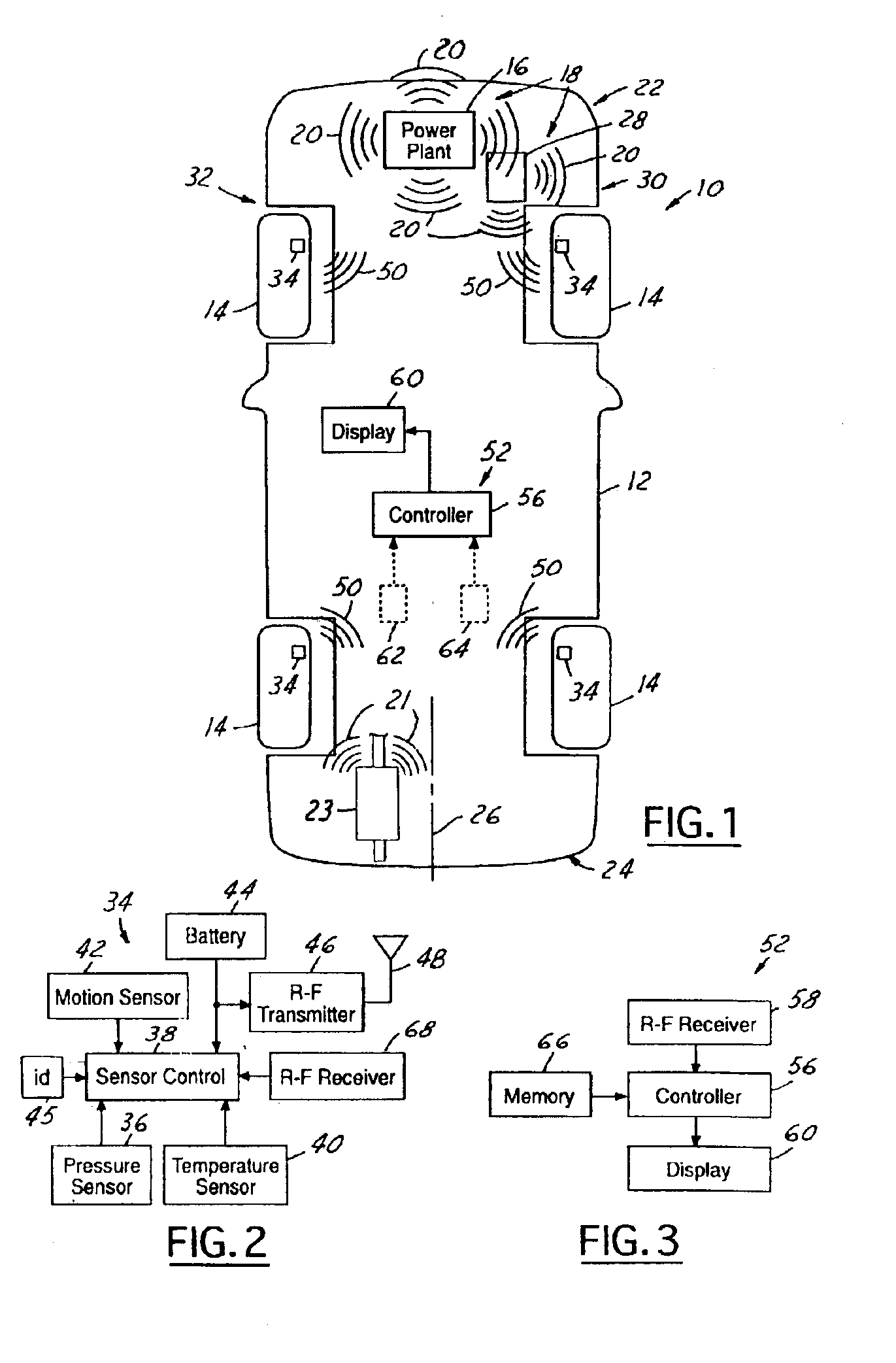
[0013]Referring now to FIG. 1, which is an illustration of an automotive tire pressure monitoring assembly 10 for use with the present invention. The automotive tire pressure monitoring assembly 10 is illustrated mounted within a vehicle 12. It is contemplated that the present invention may be utilized within a wide variety of vehicles 12 and in a wide variety of configurations. The vehicle 12 includes one or more tires 14 utilized in conjunction with a vehicle engine 16 to impart kinetic motion to the vehicle 12.

[0014]It is known that the vehicle engine / power plant 16 is one of a plurality of primary function components within an automobile that can be considered noise generating systems 18. When the vehicle engine 16 is started, a variety of noise generating systems 18 begin running simultaneously. These include, but are not limited to, charging systems, ignition systems, and switching power supplies. These systems radiate a lot of spectral noise 20 when running. It should be unde...


PUM


Abstract

An automotive tire pressure monitoring assembly 10 for installation in a vehicle 12 is provided. The automotive tire pressure monitoring assembly 10 includes at least one tire pressure sensor 34 generating a signal based on the pressure of air within a tire 14. The at least one tire pressure sensor 34 further includes a sensor receiver 68 in communication with a sensor control logic 38. The sensor control logic 38 is adapted to receive spectral noise 20 from at least one noise generating assembly 18. The automotive tire pressure monitoring assembly 10 further includes a controller assembly 52 positioned within the vehicle 12 and in remote communication with the at least one tire pressure sensor 34. The automotive tire pressure monitoring assembly 10 includes a positioning logic adapted to determine the position of the at least one tire pressure sensor 34 based on the strength of the spectral noise 20.

Description

BACKGROUND OF INVENTION[0001]The present invention relates generally to an automotive tire pressure monitoring method and assembly and more specifically to an automotive tire pressure monitoring method and assembly with auto-location features.[0002]Modern automotive performance relies on a plurality of individual vehicle components operating together. Although present vehicles often include new and increasingly complex components, many traditional components remain as crucial parameters in the vehicles operation. Such is the case with vehicle tire pressure. The air pressure within vehicle tires plays a vital role in tire performance and thereby effects proper vehicle operation. Interaction between a vehicle and its tires can effect handling, braking, rollover, and other operational characteristics. Excess tire pressure can negatively impact performance and may increase susceptibility to puncture. Low tire pressure can negatively impact performance, increase wear, and may generate ex...

Claims


Application Information

Patent Timeline
Patent Type & Authority Patents(United States)
IPC IPC(8): B60C23/04B60C23/02
CPCB60C23/045B60C23/0416
Inventor NANTZ, JOHNGHABRA, RIADTANG, TOMKING, RONALDLEMENSE, THOMAS
Owner SENSATA TECHNOLOGIES INC
Why Eureka
Try Eureka