Method and apparatus for a waking control system

Inactive Publication Date: 2005-05-03
REJUVENLY
View PDF7 Cites 127 Cited by
  • Summary
  • Abstract
  • Description
  • Claims
  • Application Information

AI Technical Summary

Benefits of technology

[0011]The principal disadvantage of the inventions described by U.S. Pat. Nos. 4,038,561, 7,234,944, 5,212,672 and 6,236,622 is that the rate and/or profile of the stimulus increase is either preset by the user or predetermined by the waking system. These techniques incorporate no feedback and are not responsive to a variable personal waking threshold, which for a given individual changes over time and is also dependant on a number of other factors. Factors that may influence an individual's personal waking thresholds include: (i) the variance in intensity that may wake different types of sleepers (i.e. light sleepers as compared to heavy sleepers); (ii) the stage of sleep that the user is in when the stimulus is introduced (i.e. stage 1, 2, 3, 4 or Rapid Eye Movement (REM)); (iii) the time that the user went to sleep (i.e. total amount of sleep that night); (iv) the phase of the user's “circadian rhythms”; (v) the amount of sleep that the user has had in the last number ofl days; (vi) the ambient stimulus level in the sleeping environment (i.e. if there is more ambient stimulus, then it will take a higher stimulus level to wake the user); and (vii) the amount of sunlight at that time of year (i.e. in the winter months, when there is less sunlight, an individual typically has higher waking thresholds). The gradual stimulus increase taught by the prior art does not necessarily match the optimal set of waking conditions for an individuals particular waking threshold at a given waking time. U.S. Pat. No. 5,928,133 (referred to herein as the '133 patent) attempts to monitor a user's sleep pattern to determine the “optimum time” to wake them. The invention incorporates a sensor comprising a pair of electrodes to measure the resistance of the user's body and to determine therefrom the user's delta waves. When individuals go through the various phases of sleep, they emit delta waves that vary in a predictable manner. At the beginning and end of each REM cycle, these delta waves exhibit spikes, where the user comes close to their waking threshold. The '133 patent allows the user to set the interval during which they want to be awoken. When the actual time reaches this predetermined waking interval, the system responds to a spike in the user's delta waves and then triggers a conventional alarm that wakes the user at that time. One drawback with the 133 patent is that it teaches a conventional alarm, having a constant stimulus level to wake the user. Even though the alarm is triggered at the “optimum time” (i.e. during spikes in the delta

Problems solved by technology

It has long been thought that such a rapid manner of waking does not promote wellness, because of the shock induced into the user's physiology by the abrupt introduction of stimuli.
The principal drawback with all of the waking devices that incorporate the snooze method is that they still involve the introduction of a constant and preset intensity of alarm stimulus, which changes almost instantaneously from an ambient level to an alarm intensity stimulus level in the manner of a step function.
The principal disadvantage of the inventions described by U.S. Pat. Nos. 4,038,561, 7,234,944, 5,212,672 and 6,236,622 is that the rate and/or profile of the stimulus increase is either preset by the user or predetermined by the waking system.
These techniques incorporate no feedback and are not responsive to a variable personal waking threshold, which for a given individual changes over time and is also dependant on a number of other factors.
The gradual stimulus increase taught by the prior art does not necessarily match the optimal set of waking conditions f

Method used


Image

  • Method and apparatus for a waking control system
  • Method and apparatus for a waking control system
  • Method and apparatus for a waking control system

Examples


Example

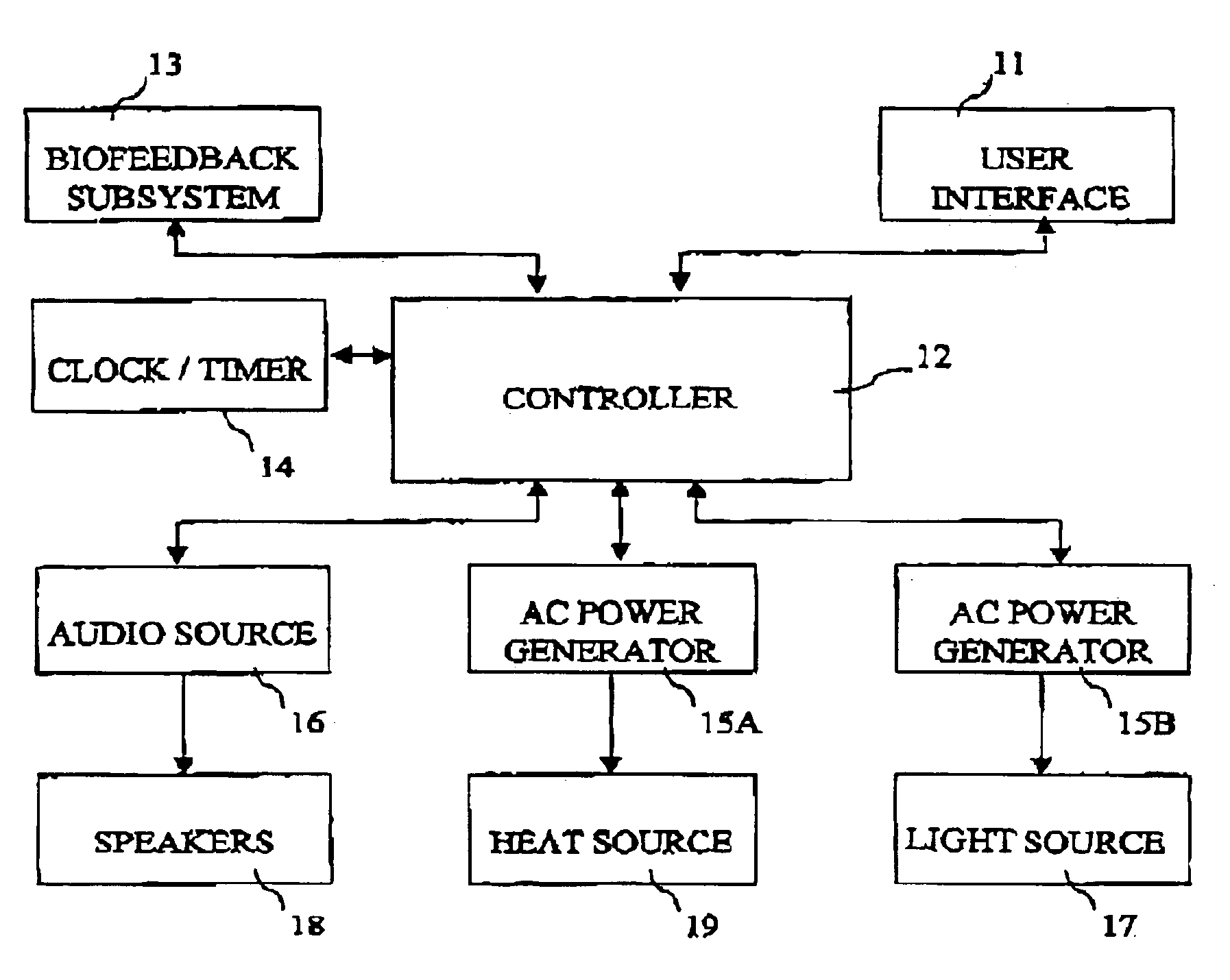
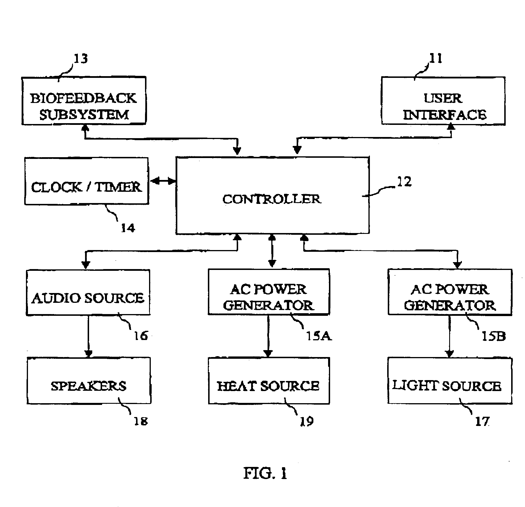
[0029]Referring to FIG. 1, a system architecture is depicted for the waking system 10 in accordance with the present invention. The waking system 10 is made up of a number of distinct subsystems and components, each of which interacts with the controller 12. The controller 12 directs the interaction of the various subsystems and components with one another and is ultimately responsible for the operation of the waking system 10. In a preferred embodiment, the controller 12 is a microprocessor, such as the PIC 16C745, which can be used in an embedded system environment. However, the invention is not dependent on the type of controller 12 that is used. Other suitable controllers include: other microprocessor chips, integrated circuit controllers, printed circuit board controllers and even computers. In general, the controller 12 should be understood to include any device capable of accessing and executing instructions stored in memory and capable of interacting with its external enviro...


PUM


Abstract

A method and apparatus are disclosed for a waking system that wakes an individual gradually over a period of time in order to promote the wellness of that individual. The user sets the system controller with a desired final wakeup time, which is the time that the user must be awake. When the actual time reaches a stimulus introduction time (i.e. some time prior to the desired final wakeup time), the system controller causes the introduction of stimulus. The system further comprises a detection system that measures a parameter correlated to the individual's sleep level (preferably motion). This measured parameter is then used in a feedback loop to control the level of stimulus experienced by the individual. In this manner, the user is woken gradually over a period of time between the stimulus introduction time and the desired final wakeup time, without introducing any sudden shocks to the user's physiological systems.

Description

FIELD OF THE INVENTION[0001]The invention described herein relates to waking devices. Specifically, the invention relates to waking devices that gradually increase stimulus to individuals so as to wake them gradually in a manner that promotes wellness.BACKGROUND OF THE INVENTION[0002]The most common waking device is the “alarm” clock. Conventional alarm clocks wake individuals by creating abrupt and sudden changes in sound, light or other stimuli, so as to shock or alarm the user, ending the sleeping process. It has long been thought that such a rapid manner of waking does not promote wellness, because of the shock induced into the user's physiology by the abrupt introduction of stimuli.[0003]Arrange of prior art has been developed to help minimize the shock introduced by conventional alarm based waking systems. One common method of reducing the shock to individuals' physiological systems is to trigger the alarm stimulus in a conventional manner and then allow the alarm stimulus to ...

Claims


Application Information

Patent Timeline
IPC IPC(8): G04G13/00G04G13/02H04L12/28
CPCA61M21/00G04G13/021H04L12/2805H05B37/0236H05B37/0281H05B37/0227Y02B20/42H05B47/12H05B47/13H05B47/16Y02B20/40
Inventor MOLLICONE, DANIEL JOSEPHVAN WOLLEN, MATTHEW VIT
Owner REJUVENLY
Why Eureka
Try Eureka