
Response virtual channel for handling all responses

a virtual channel and response technology, applied in the field of computer systems, can solve problems such as logical conflicts between packets in separate virtual channels, and achieve the effect of free operation

Inactive Publication Date: 2005-05-03
GLOBALFOUNDRIES INC
View PDF38 Cites 19 Cited by
  • Summary
  • Abstract
  • Description
  • Claims
  • Application Information

AI Technical Summary

Benefits of technology

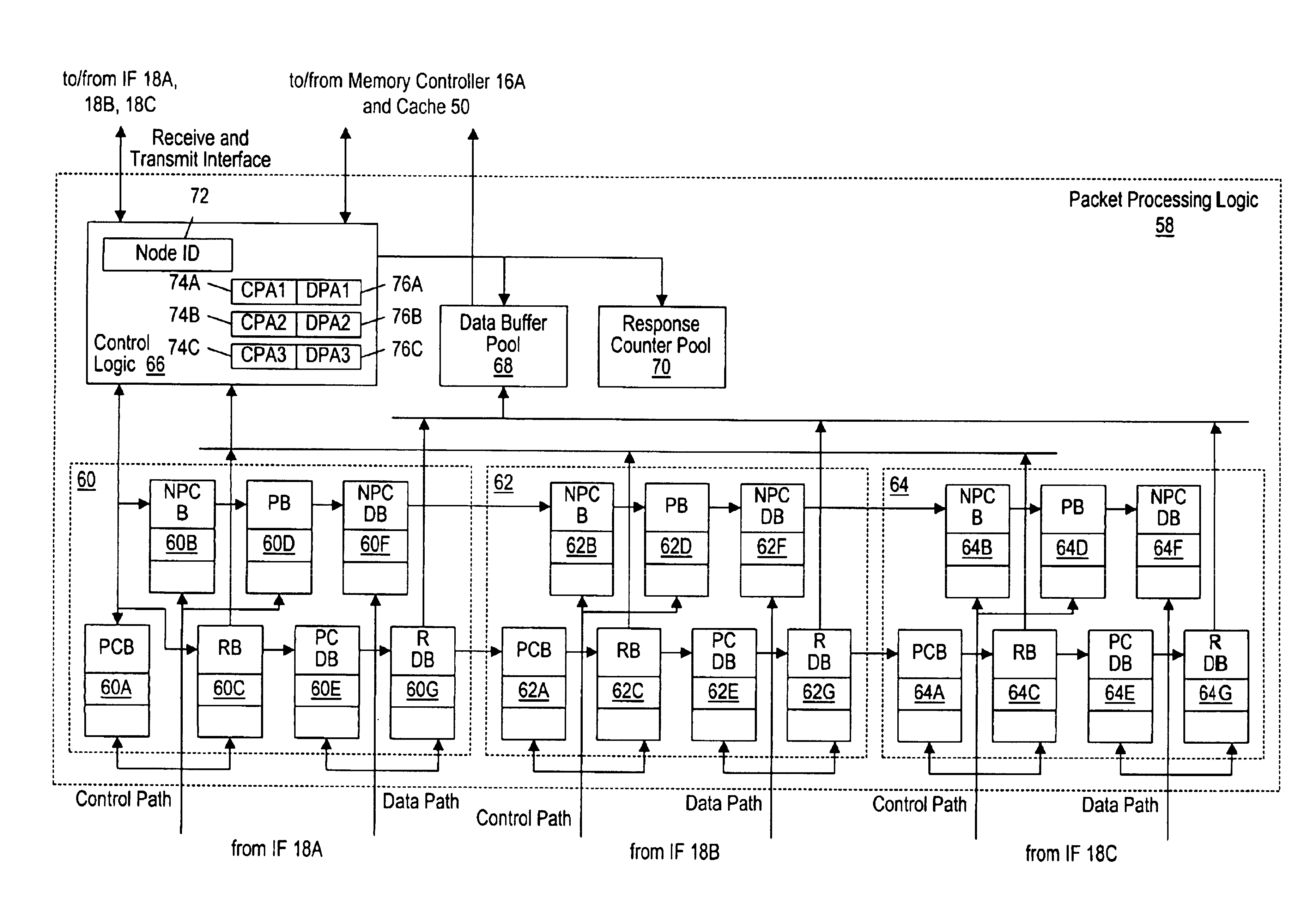
[0009]The problems outlined above are in large part solved by a computer system employing virtual channels and allocating different resources to the virtual channels as described herein. Packets which do not have logical / protocol-related conflicts are grouped into a virtual channel. Accordingly, logical conflicts occur between packets in separate virtual channels. The packets within a virtual channel may share resources (and hence experience resource conflicts), but the packets within different virtual channels may not share resources. Since packets which may experience resource conflicts do not experience logical conflicts, and since packets which may experience logical conflicts do not experience resource conflicts, deadlock-free operation may be achieved.
[0010]Additionally, nodes within the computer system may be configured to preallocate resources to process response packets. Some response packets may have logical conflicts with other response packets, and hence would normally not be allocable to the same virtual channel. However, by preallocating response-processing resources, response packets are accepted by the destination node. Thus, any resource conflicts which may occur are temporary (as the response packets which make forward progress are processable). Viewed in another way, response packets may be logically independent if the destination node is capable of processing the response packets upon receipt. Accordingly, a response virtual channel is formed to which each response packet belongs. Since fewer virtual channels are used, fewer resources are used to support the virtual channels, and hence the amount of hardware used to support the virtual channels is decreased.

Problems solved by technology

Accordingly, logical conflicts occur between packets in separate virtual channels.
The packets within a virtual channel may share resources (and hence experience resource conflicts), but the packets within different virtual channels may not share resources.

Method used


Image

  • Response virtual channel for handling all responses
  • Response virtual channel for handling all responses
  • Response virtual channel for handling all responses

Examples


Embodiment Construction

System Overview

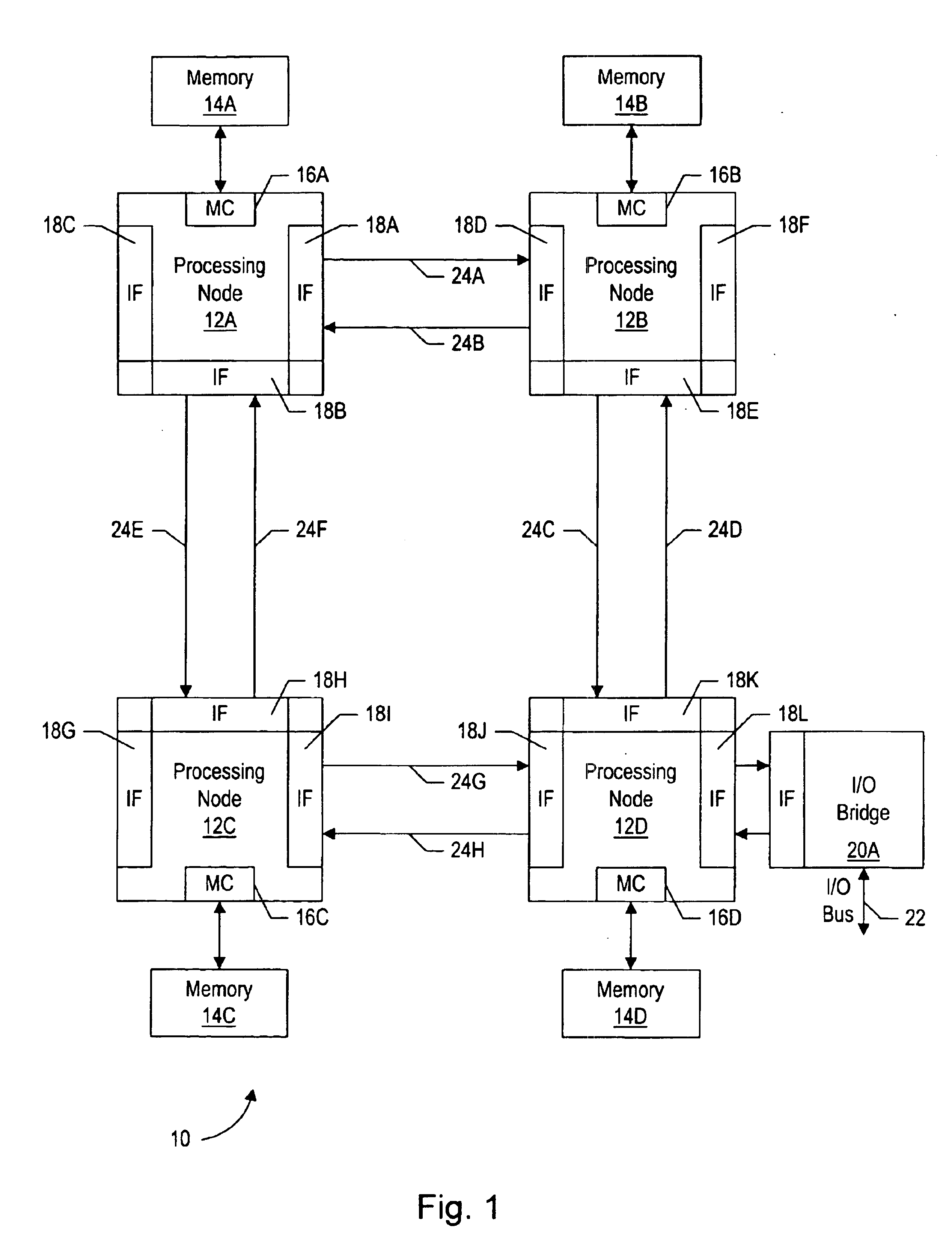
[0043]Turning now to FIG. 1, one embodiment of a computer system 10 is shown. Other embodiments are possible and contemplated. In the embodiment of FIG. 1, computer system 10 includes several processing nodes 12A, 12B, 12C, and 12D. Each processing node is coupled to a respective memory 14A-14D via a memory controller 16A-16D included within each respective processing node 12A-12D. Additionally, processing nodes 12A-12D include interface logic used to communicate between the processing nodes 12A-12D. For example, processing node 12A includes interface logic 18A for communicating with processing node 12B, interface logic 18B for communicating with processing node 12C, and a third interface logic 18C for communicating with yet another processing node (not shown). Similarly, processing node 12B includes interface logic 18D, 18E, and 18F; processing node 12C includes interface logic 18G, 18H, and 18I; and processing node 12D includes interface logic 18J, 18K, and 18L. Pro...


PUM


Abstract

A computer system employs virtual channels and allocates different resources to the virtual channels. Packets which do not have logical / protocol-related conflicts are grouped into a virtual channel. Accordingly, logical conflicts occur between packets in separate virtual channels. The packets within a virtual channel may share resources (and hence experience resource conflicts), but the packets within different virtual channels may not share resources. Since packets which may experience resource conflicts do not experience logical conflicts, and since packets which may experience logical conflicts do not experience resource conflicts, deadlock-free operation may be achieved. Additionally, nodes within the computer system may be configured to preallocate resources to process response packets. Some response packets may have logical conflicts with other response packets, and hence would normally not be allocable to the same virtual channel. However, by preallocating response-processing resources, response packets are accepted by the destination node. Thus, any resource conflicts which may occur are temporary (as the response packets which make forward progress are processable). Viewed in another way, response packets may be logically independent if the destination node is capable of processing the response packets upon receipt. Accordingly, a response virtual channel is formed to which each response packet belongs.

Description

BACKGROUND OF THE INVENTION[0001]1. Field of the Invention[0002]This invention is related to the field of computer systems and, more particularly, to interconnect between nodes in computer systems.[0003]2. Description of the Related Art[0004]Generally, personal computers (PCs) and other types of computer systems have been designed around a shared bus system for accessing memory. One or more processors and one or more input / output (I / O) devices are coupled to memory through the shared bus. The I / O devices may be coupled to the shared bus through an I / O bridge which manages the transfer of information between the shared bus and the I / O devices, while processors are typically coupled directly to the shared bus or are coupled through a cache hierarchy to the shared bus.[0005]Unfortunately, shared bus systems suffer from several drawbacks. For example, since there are multiple devices attached to the shared bus, the bus is typically operated at a relatively low frequency. The multiple at...

Claims


Application Information

Patent Timeline
IPC IPC(8): G06F13/40
CPCG06F13/405
Inventor KELLER, JAMES B.MEYER, DERRICK R.
Owner GLOBALFOUNDRIES INC
Learn More