
Low-cost, high precision goniometric stage for x-ray diffractography

Inactive Publication Date: 2005-05-03
ADVANCED DESIGN COSULTING USA
View PDF13 Cites 21 Cited by
  • Summary
  • Abstract
  • Description
  • Claims
  • Application Information

AI Technical Summary

Benefits of technology

[0018]Yet another object of the invention is to reduce the mass of the stage and thereby increase the speed of response.
[0019]Still yet another object of the invention is to reduce the size of the stage.
[0020]Another object of the invention is to lower the cost of the stage.
[0021]Another object of the invention is to simplify maintenance and increase the reliability of the stage.
[0022]A further object of the invention is to easily scale the device for larger loads, greater accuracy, faster response, etc.
[0024]In accordance with a preferred embodiment of the invention, there is disclosed a low-cost, high precision goniometric stage for x-ray diffractography, or for use in optical systems, comprising: a spherical sector supported on at least one bearing, a top surface of said spherical sector that is used for mounting a sample or device, a center of rotation located above said top surface, a rod or other member that is disposed below the spherical bearing surface, preferably orthogonal to the rotational axes, stepper motors or other means to move the device and a mechanical linkage between the rod and the means to move the device.

Problems solved by technology

Neither the resolution nor the size of the stage are, however, satisfactory.
Existing designs for goniometers are unnecessarily large, complex and costly.
Excepting Smith et al all of the devices that utilize a spherical bearing surface rely on direct surface to surface contact which, due to static frictional forces, reduces their precision.
Gimbal type mounts and those optical mounts with spherical bearings are not suitable since the axes of rotation are below the sample.
This necessitates simultaneous in-plane and vertical adjustments when used for x-ray diffractography and introduces additional positioning error.
It is still, however, unnecessarily large and complex and requires vertical correction.

Method used


Image

  • Low-cost, high precision goniometric stage for x-ray diffractography
  • Low-cost, high precision goniometric stage for x-ray diffractography
  • Low-cost, high precision goniometric stage for x-ray diffractography

Examples


Embodiment Construction

[0029]Detailed descriptions of the preferred embodiment are provided herein. It is to be understood, however, that the present invention may be embodied in various forms. Therefore, specific details disclosed herein are not to be interpreted as limiting, but rather as a basis for the claims and as a representative basis for teaching one skilled in the art to employ the present invention in virtually any appropriately detailed system, structure or manner.

[0030]In order to ease understanding the various drawings use like reference members to represent like parts of the invention.

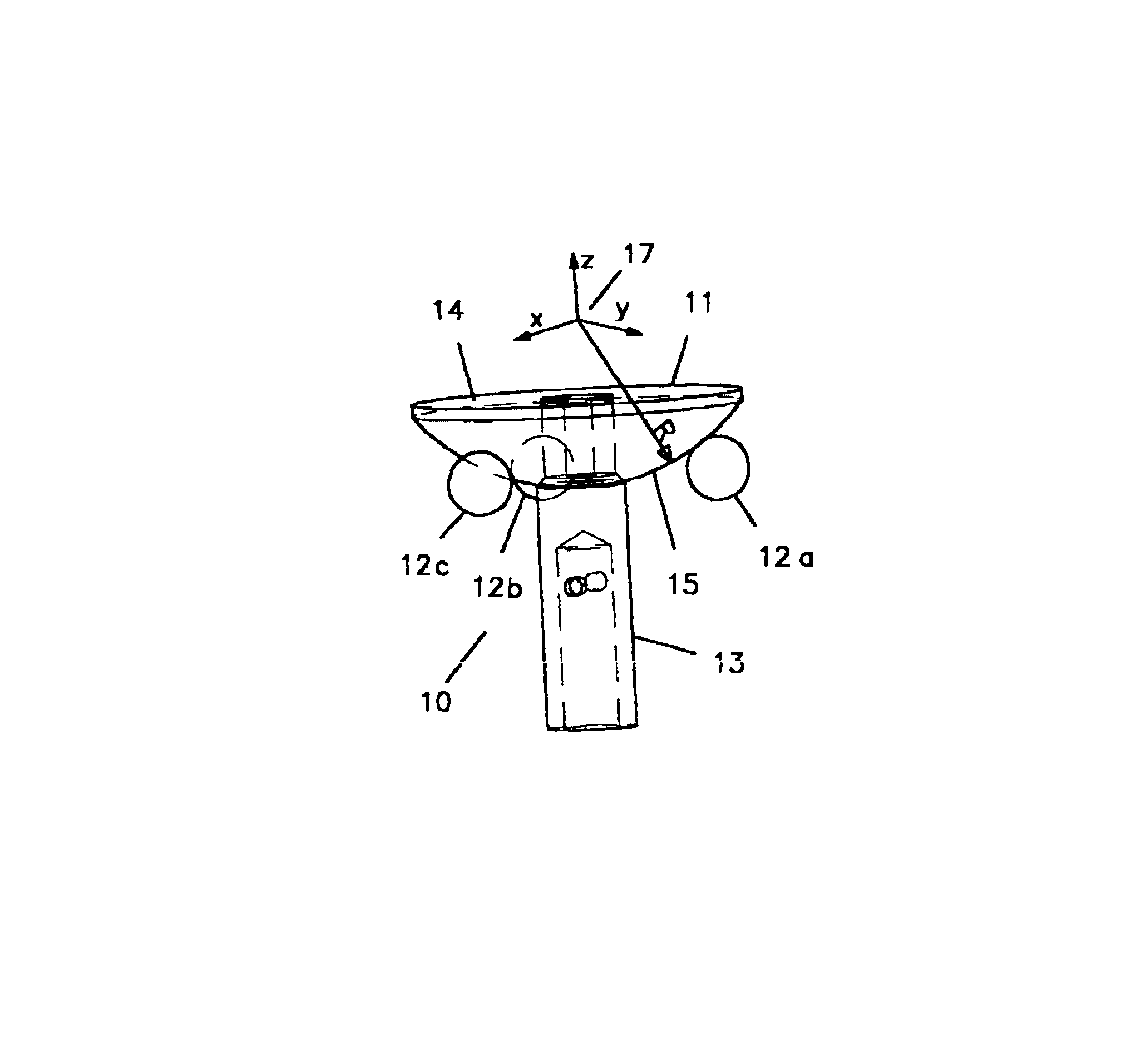
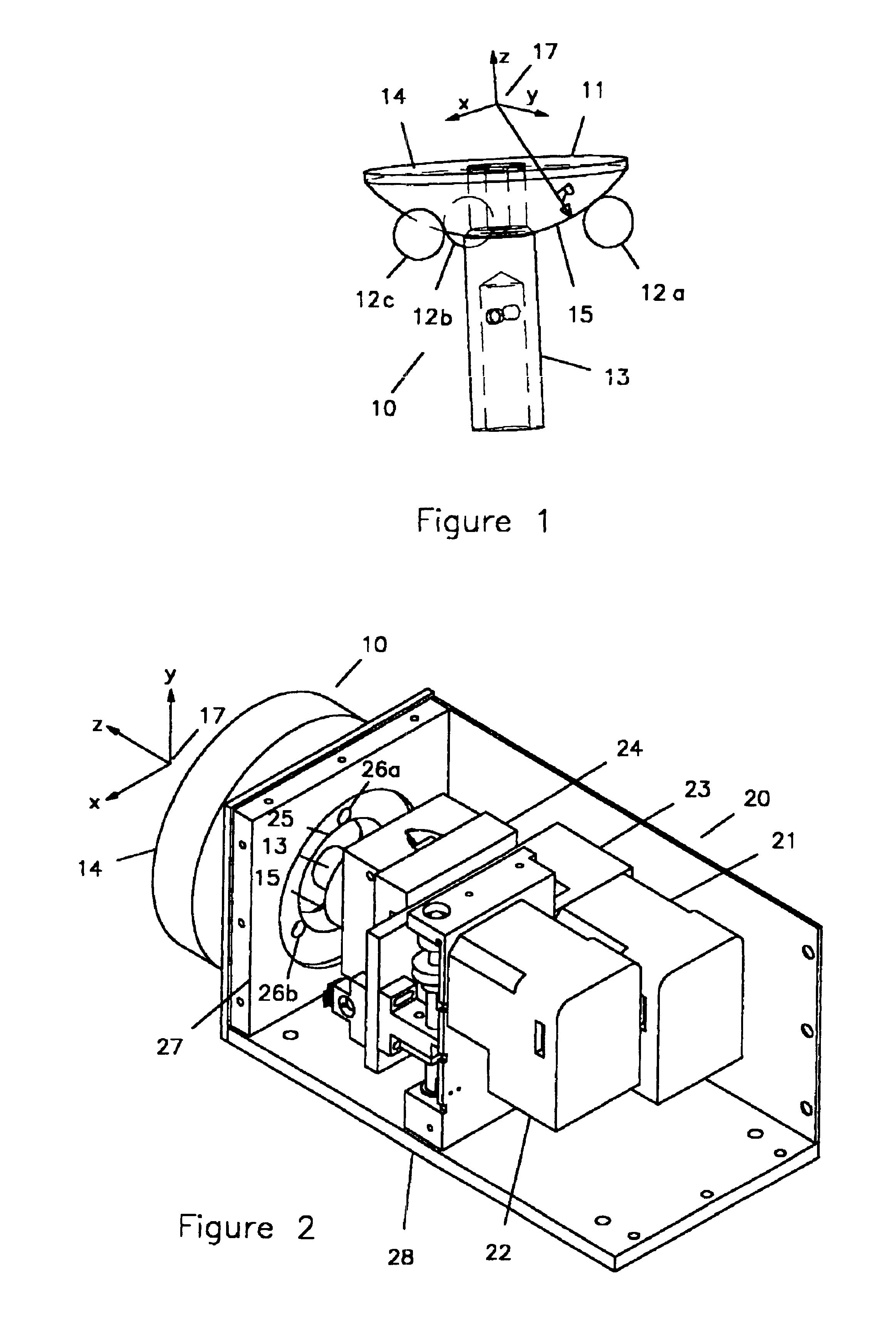
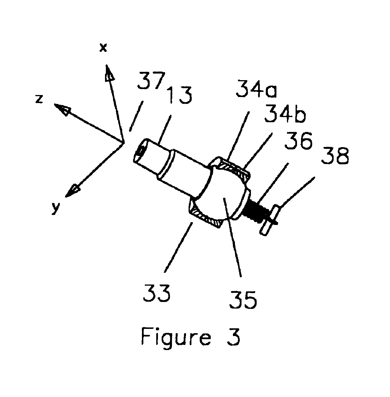
[0031]In accordance with the present invention FIG. 1 shows a preferred embodiment of the goniometer bearing assembly 10 for use in x-ray diffractography. Directions x, y, and z, used in the description, are indicated by the right-hand, orthogonal triad 17 which is located at the center of rotation of the bearing assembly 10. A spherical sector 11, made from a hardened steel or other material, preferably with ...


PUM


Abstract

A low-cost, high precision goniometric stage, for use in x-ray diffractography or in optical systems, with a spherical sector supported on at least one bearing, a top surface of the spherical sector that is used for mounting an object, a center of rotation located within the object, a rod or other member that is disposed below the spherical bearing surface, preferably orthogonal to the rotational axes, stepper motors or other actuators to move the device and a mechanical linkage between the rod and the motors.

Description

CROSS REFERENCE TO RELATED APPLICATIONS[0001]Not ApplicableSTATEMENT REGARDING FEDERALLY SPONSORED RESEARCH OR DEVELOPMENT[0002]Not ApplicableDESCRIPTION OF ATTACHED APPENDIX[0003]Not ApplicableBACKGROUND OF THE INVENTION[0004]This invention relates generally to the field of motion systems and more specifically to a low-cost, high precision goniometric stage for use in x-ray diffracto-graphy or optical systems. Goniometers have been used for many years to measure angular relationships begriming with Wollaston's goniometer (1807) for measuring the angle between crystal faces. Recently single-tilt and double-tilt sample holders have been widely used in electron microscopy and in x-ray diffractometers. In most applications the goniometer rotates a sample around two axes and is often coupled with rotational and translational stages to provide up to six degrees of freedom.[0005]As x-ray diffractography has advanced the need for precise sample positioning has become more stringent. Analyz...

Claims


Application Information

Patent Timeline
IPC IPC(8): G01N23/20
CPCG01N23/20016G21K1/06
Inventor BLANK, BASIL ERICDEYHIM, ALEXANDER KHOSRO
Owner ADVANCED DESIGN COSULTING USA
Learn More