Photonic crystal fibres

a technology crystal fibres, which is applied in the field of photonic crystal fibres, can solve the problems of inability to directly use photonic crystal fibres, the method of birefringence produced by standard fibres, and the inability to control the polarisation of propagating light in single-mode optical fibres. to achieve the effect of reducing the scal

Inactive Publication Date: 2005-05-03
CRYSTAL FIBRE AS
View PDF22 Cites 35 Cited by
  • Summary
  • Abstract
  • Description
  • Claims
  • Application Information

AI Technical Summary

Benefits of technology

[0040]In the new method, substantial and controlled changes may occur in the fibre structure while it is being drawn; for example, there may also be controlled expansion of the ai

Problems solved by technology

However, even so-called single-mode optical fibres do not generally offer adequate control over the polarisation of propagating light.
The methods used to produce birefringence in standard fibres, and thus to produce standard polarisation-preserving fibres, are, in general, not directly suitable for use in photonic-crystal fibre.
As is the case in a real fibre with circular symmetry, imperfections in the fibre will result in power transfer between modes polarised parallel to each of tho

Method used


Image

  • Photonic crystal fibres
  • Photonic crystal fibres
  • Photonic crystal fibres

Examples


Embodiment Construction

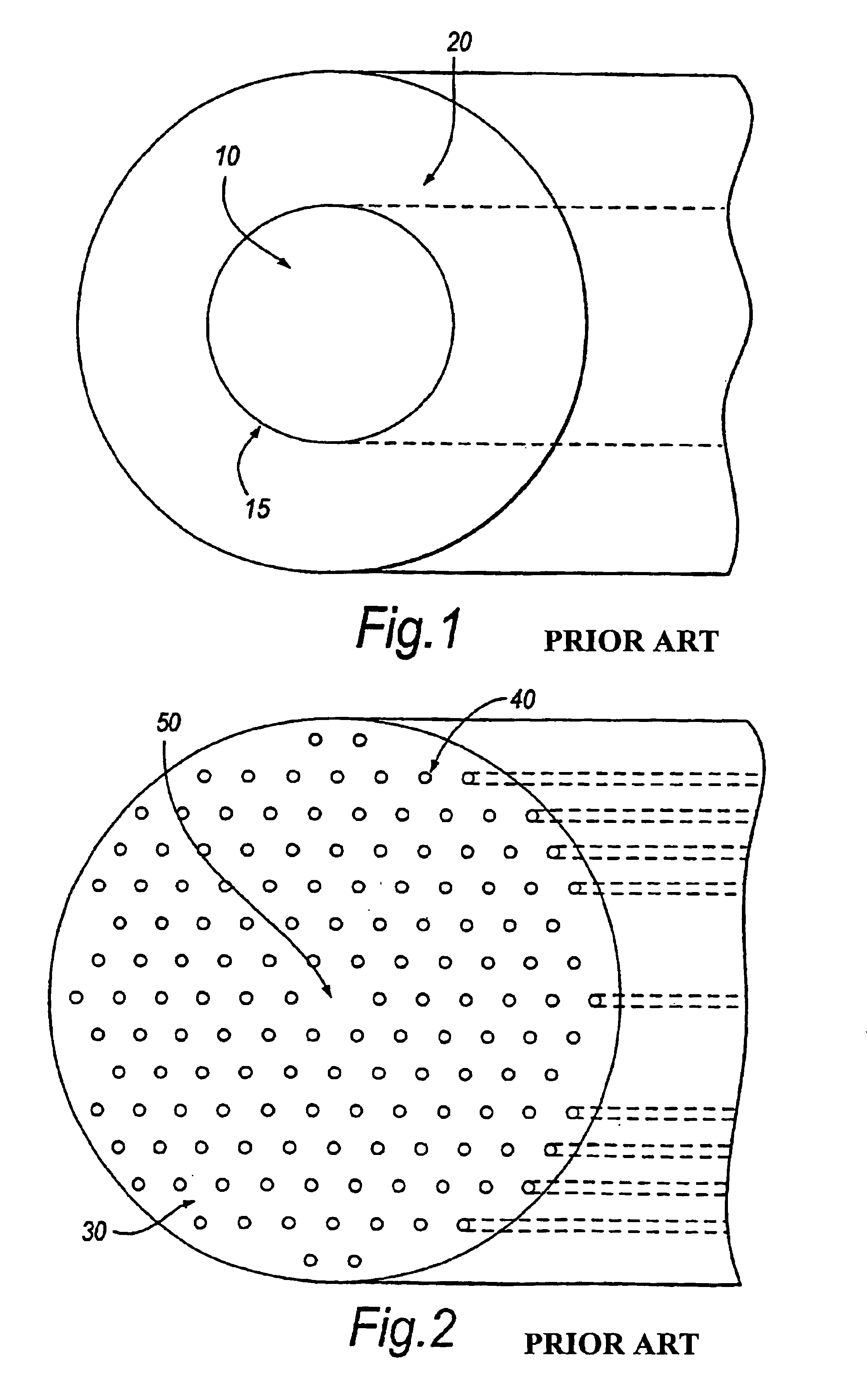
[0071]Standard fibres, such as the example shown in FIG. 1, in their simplest form comprise essentially a cylindrical core 10 and concentric cylindrical cladding 20. Typically, both the core and the cladding will be made of the same material, usually silica, but each is doped with other materials in order to raise the refractive index of the core 10 and lower the refractive index of the cladding 20. Light, of appropriate wavelengths, is confined to the core 10, and guided therein, by total internal reflection at the core-cladding boundary 15.

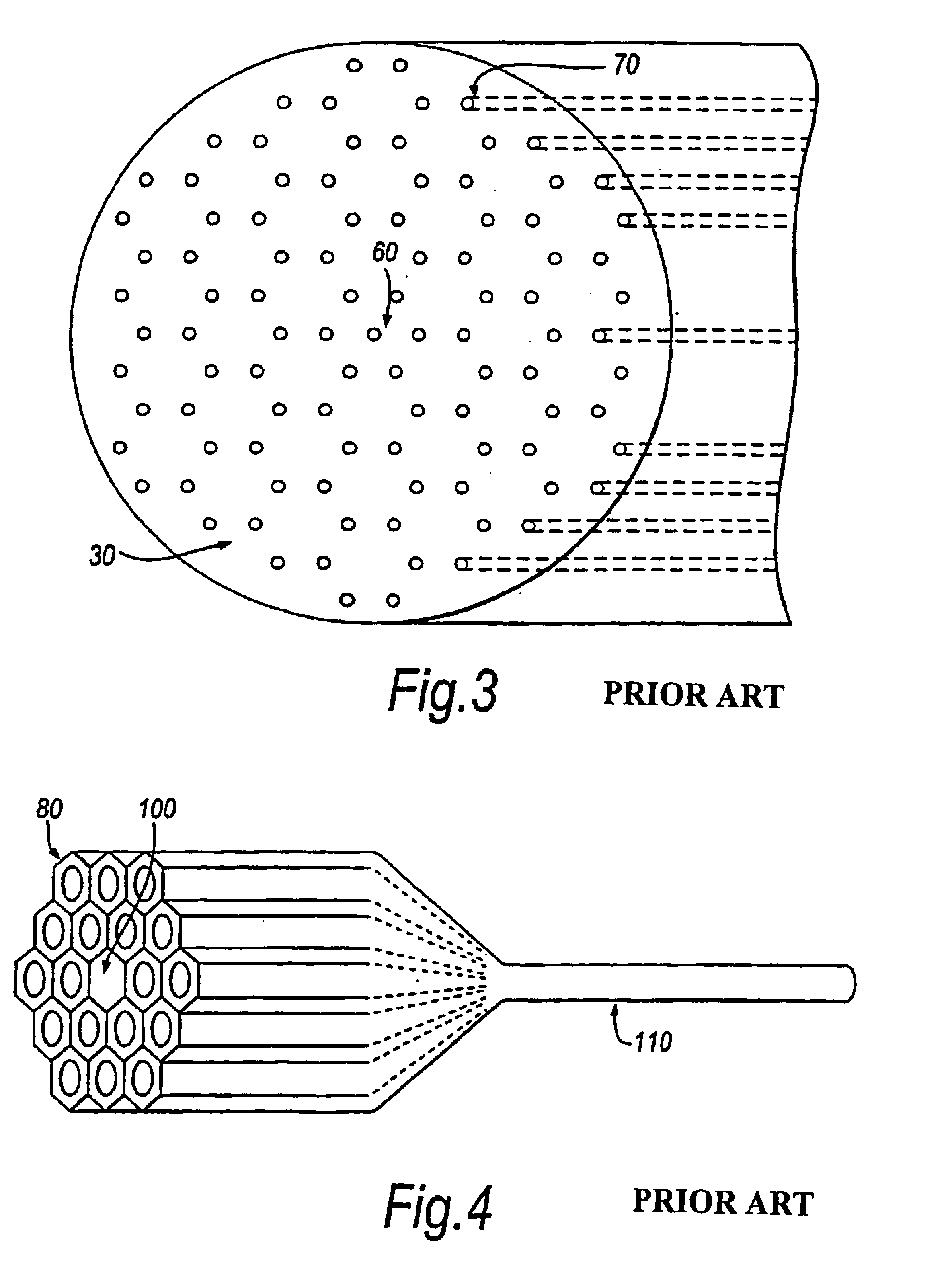
[0072]A typical photonic crystal fibre, shown in FIG. 2, comprises a cylinder of transparent bulk material 30 (e.g. silica) with a lattice of cylindrical holes 40, which run along its length. The holes are arranged at the vertices and centres of regular hexagons, which have six-fold rotational symmetry. The holes have a regular period, broken by the omission of one hole near the centre of the fibre. The region 50 of the fibre surrounding the sit...


PUM

PropertyMeasurementUnit
Pressureaaaaaaaaaa
Lengthaaaaaaaaaa
Internal pressureaaaaaaaaaa

Abstract

In a method of producing a photonic crystal fibre, a preform (300) that includes holes is formed and the preform (300) is drawn into a fibre. The method includes the step of applying a pressure differential to certain of the holes to control changes in the fibre structure during the draw.

Description

CROSS-REFERENCE TO RELATED APPLICATIONS[0001]The present application is a continuation of U.S. patent application Ser. No. 09 / 890,793, file date Nov. 8, 2001 which is a national phase application of PCT Application No. PCT / GB00 / 00600 filed Feb. 18, 2000. The contents of U.S. patent application Ser. No. 09 / 890,793 and PCT / GB00 / 00600 are hereby incorporated herein by reference.FIELD OF THE INVENTION[0002]This invention relates to photonic crystal fibres and to a method of producing photonic crystal fibres.BACKGROUND OF THE INVENTION[0003]A photonic crystal fibre is a special form of optical fibre. Optical fibres are used in many fields including telecommunications, laser machining and welding, laser beam and power delivery, fibre lasers, sensors and medical diagnostics and surgery. They are typically made entirely from solid transparent materials such as glass and each fibre typically has the same cross-sectional structure along its length. The transparent material in one part (usuall...

Claims


Application Information

Patent Timeline
IPC IPC(8): C03B37/02C03B37/012C03B37/075C03B37/027C03B37/028G02B6/28G02B6/10G02B6/255G02B6/02G02B6/122
CPCB82Y20/00C03B37/02781C03B37/0122C03B37/02709C03B37/0756G02B6/02347G02B6/02352G02B6/02357G02B6/02361G02B6/02371G02B6/0238G02B6/105G02B6/1225G02B6/2551G02B6/2552G02B6/2835C03B37/027C03B37/01217C03B2203/14C03B2203/30C03B2203/42C03B2205/08C03B2205/10G02B6/12
Inventor RUSSELL, PHILIP ST. JOHNBIRKS, TIMOTHY ADAMKNIGHT, JONATHAN CAVE
Owner CRYSTAL FIBRE AS
Why Eureka
Try Eureka