Heat cutoff signal transmission unit and superconducting signal transmission apparatus

a transmission unit and signal technology, applied in the direction of electrical equipment, superconductors/hyperconductors, waveguides, etc., can solve the problems of not being suited for mass production, taking up manufacturing, and increasing costs, and achieve suppression of heat flow and low heat conductivity

Inactive Publication Date: 2005-05-03
FUJITSU LTD
View PDF17 Cites 7 Cited by
  • Summary
  • Abstract
  • Description
  • Claims
  • Application Information

AI Technical Summary

Benefits of technology

[0017]is characterized by being comprised of a flat circuit body provided with a substrate and with a signal transmission line and a ground layer both formed on this substrate, where the substrate is comprised of a dielectric material having a low heat conductivity and where conductor portions forming the signal transmission line and ground layer are formed with a thin thickness enabling suppression of the flow of heat from the outside.

Problems solved by technology

There are however the following problems in the above prior art devices:
(i) Since it is necessary to make a special coaxial cable having a special heat cutoff structure, there is the problem that time is taken for the manufacture and therefore the cost becomes higher.
Therefore, this is not suited for mass production.
(ii) If adopting a heat cutoff structure for reducing the thickness of the outer conductor of the coaxial cable, when combining the coaxial cable, superconducting electronic device, and cooling use vacuum container to assemble a single superconducting signal transmission apparatus, there is insufficient flexibility for freely deforming the coaxial cable and therefore there is the problem that assembly becomes difficult.
This is due to the fact that a thin outer conductor ends up easily cracking due to bending or other deformation.
(iii) Further, there is the problem that a thin outer conductor ends up peeling off due to vibration transmitted from the cooling refrigeration machine.
(iv) Further, since the above special heat cutoff structure is used only at the outer conductor side of the coaxial cable, there is the problem that there is no heat cutoff effect at all for the flow of heat through the center conductor of the coaxial cable.
Therefore, the superconducting state can no longer be maintained at the junction of the center conductor and superconducting electronic device and contact resistance is liable to be generated.

Method used


Image

  • Heat cutoff signal transmission unit and superconducting signal transmission apparatus
  • Heat cutoff signal transmission unit and superconducting signal transmission apparatus
  • Heat cutoff signal transmission unit and superconducting signal transmission apparatus

Examples


Embodiment Construction

[0031]To further facilitate understanding of the present invention, first an explanation will be given of the several conventional examples mentioned above.

[0032]FIG. 8 gives sectional vies of coaxial cables having heat cutoff structures according to a conventional first example (a), second (b), and third example (c).

[0033]The first example corresponds to the above-mentioned Japanese Unexamined Patent Publication (Kokai) No. 9- 129041, the second example to the above-mentioned Japanese Unexamined Patent Publication (Kokai) No. 9- 134618, and the third example to the above-mentioned Japanese Unexamined Patent Publication (Kokai) No. 9- 147634.

[0034]In (a), (b), and (c) of FIG. 8, reference numberal 1 indicates a coaxial cable w a center conductor, and 3 a dielectric. Further, 4, 4′, and 4″ indicate outer conductors of the first, second, and third examples.

[0035]In FIG. 8(a), the outer conductor 4 is configured by a thin, that is, small sectional area metal film so as to obtain a heat...


PUM

PropertyMeasurementUnit
cryogenic temperatureaaaaaaaaaa
temperatureaaaaaaaaaa

Abstract

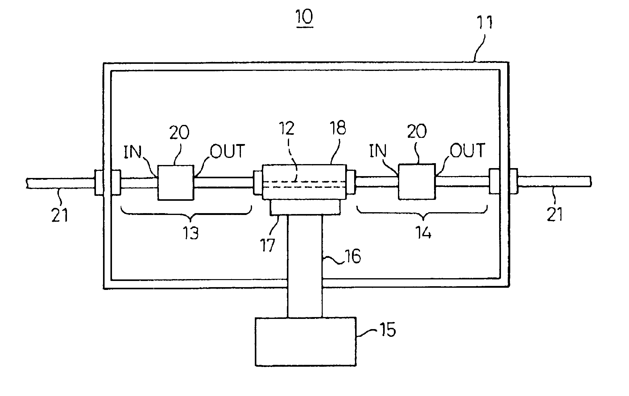
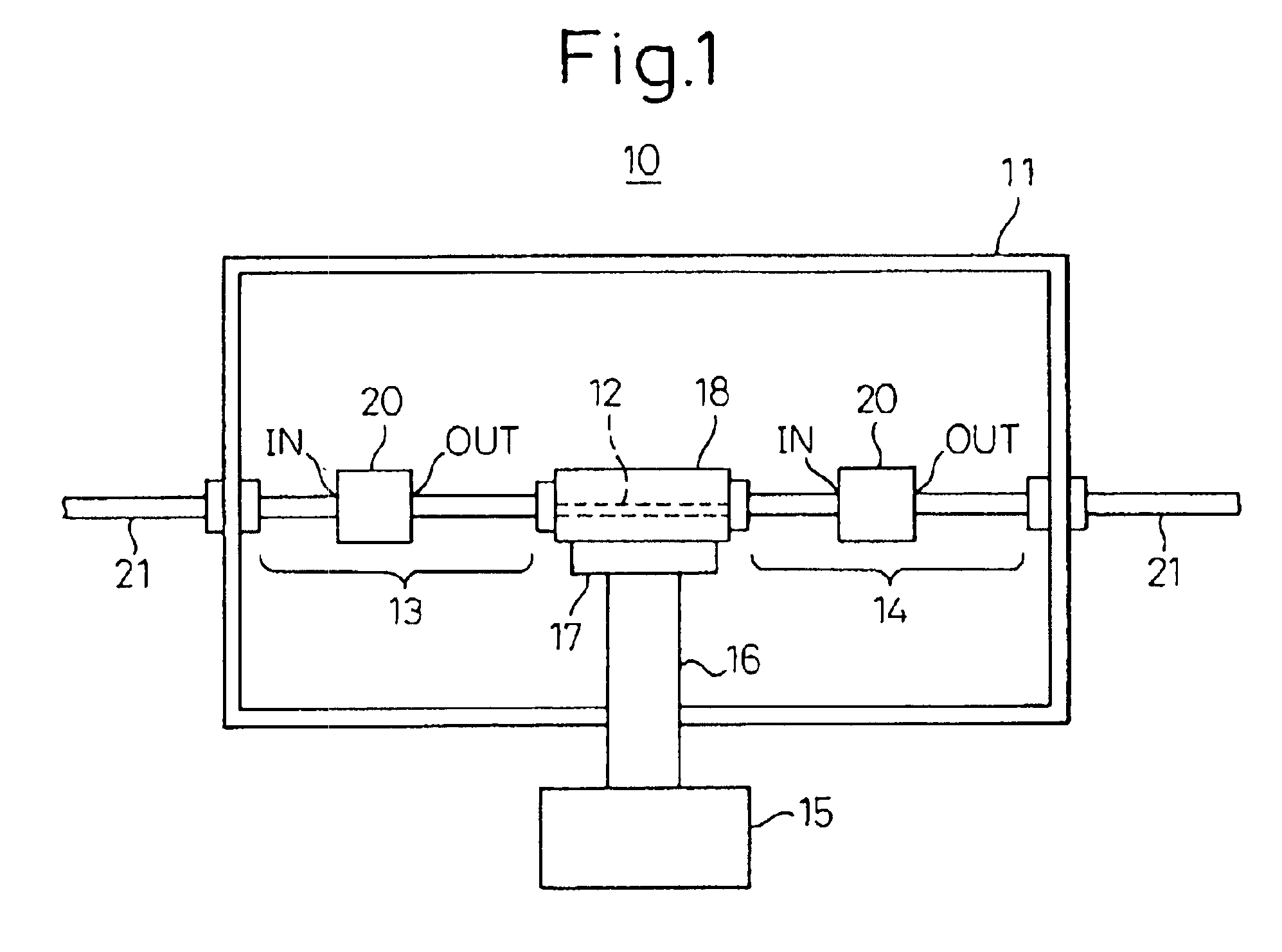
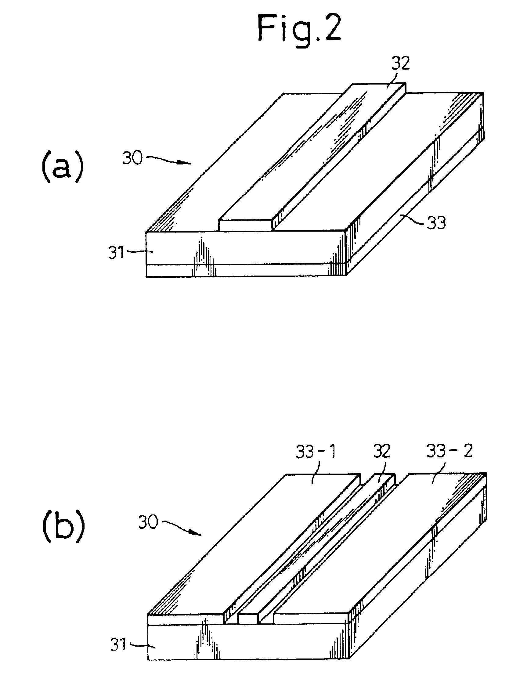
A superconducting signal transmission apparatus provided with a vacuum container 11, a superconducting electronic device 12 provided in the vacuum container 11, an input side transmission line 13 and output side transmission line 14 for connection to the superconducting electronic device 12 through the vacuum container 11, and a cooling mechanism (15, 16, 17) for cooling the superconducting electronic device 12 and further having a heat cutoff signal transmission unit 20 inserted at least at part of the input side and output side transmission lines 13 and 14. The heat cutoff signal transmission unit 20 is comprised of a substrate 31 and a flat circuit body 30 provided with a signal transmission line 32 and ground layer (33, 33-1, 33-2). The substrate 31 is comprised of a dielectric material having a small heat conductivity. The conductor portions forming the signal transmission line 32 and the ground layer are formed with thin thicknesses enabling suppression of the inflow of heat from the outside.

Description

CROSS-REFERENCE TO RELATED APPLICATION[0001]This application is a continuation application and is based upon PCT / JP00 / 00524, filed on Jan. 31, 2000.TECHNICAL FIELD[0002]The present invention relates to a heat cutoff signal transmission unit for maintaining a superconducting electronic device operating at a cryogenic temperature efficiently in a cryogenic state and a superconducting signal transmission apparatus using the same.[0003]Recently, superconducting electronic devices operating under a superconducting state have received interest and attention. As such electronic devices, there are for example the superconducting filters able to be used for transceiver apparatuses of base stations in mobile communication systems. Alternatively, there are also SQUID fluxmeters used for measurement of electroencephalograms in medical systems.[0004]Cooling such superconducting electronic devices to less than the cryogenic temperature of 70K requires a considerably large-scale refrigeration mach...

Claims


Application Information

Patent Timeline
Patent Type & Authority Patents(United States)
IPC IPC(8): H01P1/30H01P3/08H04B1/02H04B1/036H01P3/00H01P3/06
CPCH01P1/30H01P3/003H01P3/06H01P3/088Y10S505/703H04B1/036Y10S505/70Y10S505/706
Inventor KAI, MANABUMANIWA, TORUYAMANAKA, KAZUNORIAKASEGAWA, AKIHIKO
Owner FUJITSU LTD
Why Eureka
Try Eureka