Method for processing surface and apparatus for processing same

a processing surface and surface technology, applied in process and machine control, process control, instruments, etc., can solve the problems of large tolerance of actual removal depth with respect to target removal depth, affecting processing precision, and relationship described above not being corrected in response to the shape of processed surface, etc., to achieve high curved surface precision

Inactive Publication Date: 2005-05-03
RICOH KK
View PDF9 Cites 6 Cited by
  • Summary
  • Abstract
  • Description
  • Claims
  • Application Information

AI Technical Summary

Benefits of technology

[0016]Still another object of the present invention is to realize a printing apparatus capable of high-speed and high-definition printing, on which an optical device molded by use of the metal mold for the optical device is mounted, the metal mold being obtained by the curved surface processing method and the curved surface processing apparatus of the present invention.
[0022]For the objective matter for polishing processing, information in the polishing processing (information regarding such as the relationship between the processing condition and the removal quantity or the removal depth, which is obtained by processing the reference surface of the material as that of the processed surface) is obtained by actual processing. Based on the information, and the relationship between the processing condition and the removal quantity or the removal depth in the reference surface is corrected in accordance with the shape of the worked surface, then the load, the tool peripheral velocity and the like in the polishing processing are controlled. Thus, the worked surface can be finished in high curved surface precision in one polishing processing. Then, the control information is obtained for each processed matter different in shape, and the polishing control is performed similarly, thus making it possible to perform the polishing processing in similar precision irrespective of any shape of the polished worked surface.

Problems solved by technology

On the other hand, in the case where a free curved surface of an device in an optical field, a mold (or a piece of the mold) or the like is polished precisely, which has a curvature radius smaller than that of the mirror for X-rays, it has been found out that there occurs a problem of a large tolerance of an actual removal depth with respect to a target removal depth if the curvature radius is reduced (a value of the curvature is isolated from zero) as shown in FIG.
Moreover, particularly in a free curved surface in which a large change of the curvature radius such as a change from the convex surface to the concave surface is present, the above-described tolerance greatly affects the processing precision.
However, the relationship described above has not been corrected in response to the shape of the processed surface, and particularly, to the curvature radius.
Therefore, high-precision processing cannot be performed.
In this method, since the processed surface is contaminated by cuttings, abrasive grains or the like, the measuring precision has limitations.
Accordingly, the processing precision based on the measurement result also has limitations naturally.
As described above, each of the related prior arts has limitations in processing precision, and convergence of the processing precision also has limitations.
Therefore, each of the related arts is still insufficient for realizing the high-precision processing while reducing the variations of the processing precision as much as possible.

Method used


Image

  • Method for processing surface and apparatus for processing same
  • Method for processing surface and apparatus for processing same
  • Method for processing surface and apparatus for processing same

Examples


embodiment 1

[0052](Embodiment 1)

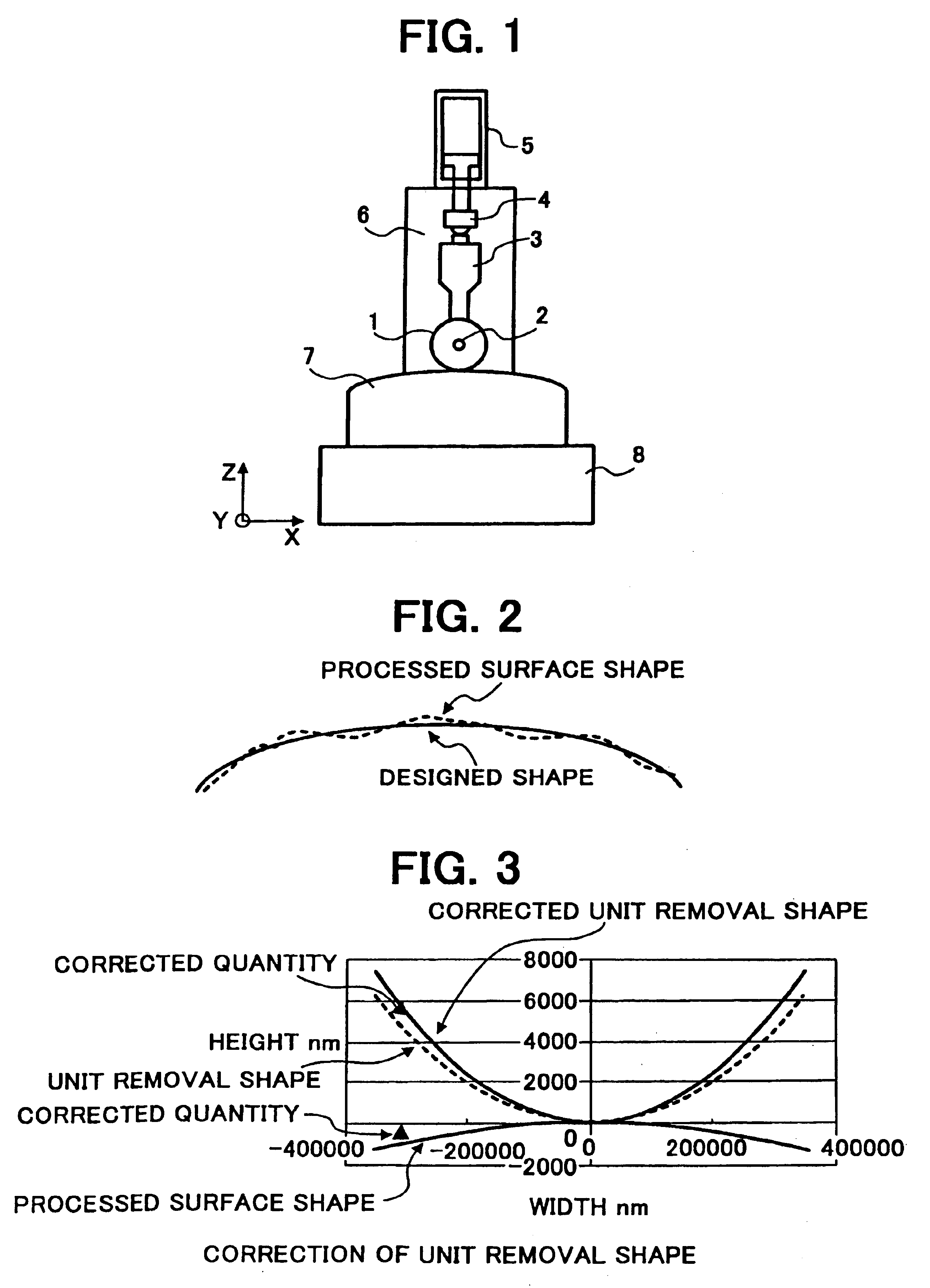
[0053]When a convex spherical surface having a curvature radius of 50 mm is processed, a unit removal shape obtained by processing a plane, for example, a removal shape formed by thrusting a rotating tool against the plane for one second under a specified condition, is corrected to cope with the curvature radius of 50 mm. As shown in FIG. 3, the unit removal shape is disposed so as to abut by vertex against the convex spherical surface having the curvature radius of 50 mm, and the unit removal shape is deformed in the same direction as a vertical direction (normal direction) and by the same quantity as a moving quantity, the vertical direction and the moving quantity being observed when the convex spherical surface is developed into a plane. A result obtained by such deformation is shown in a graph of a unit removal shape after correction. An axis of ordinates indicates a depth of the removal shape, where a unit removal shape having a depth of about 6 μm is corre...

embodiment 2

[0057](Embodiment 2)

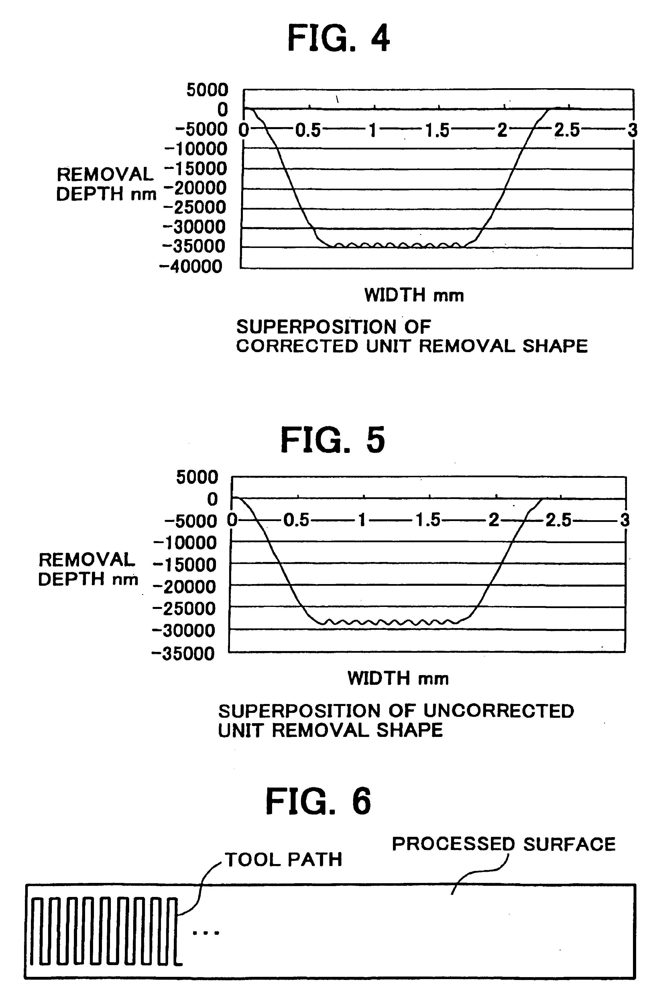
[0058]FIG. 6 shows a metal mold for molding a long-scale optical device. In this case, processing is performed on a tool path as illustrated. The worked surface is a free curved surface, where the curvature radius is changed depending on a position of the worked surface. There is a processed area having a length of about 200 mm in the main scanning direction and a length of about 3 mm in the sub-scanning direction. The curvature radii with respect to two directions of the main and sub scanning directions perpendicular to each other for an area divided into 40 sections in the main scanning direction are obtained by use of a computer. Here, coordinates of three points arrayed on a main bus-bar in an area 1 shown in FIG. 7 are first calculated by use of the following design equations.

(X1−a)2+(Z1−b)2=R2  Equation (1)

(X2−a)2+(Z2−b)2=R2  Equation (2)

(X3−a)2+(Z3−b)2=R2  Equation (3) [0059]where a and b are constants, R is a curvature radius,

b={(X1+X2)(X2−X3)(X1−X2)+(Z...

embodiment 3

[0062](Embodiment 3)

[0063]FIG. 6 shows the metal mold for molding the long-scale optical device. In this case, processing is performed on the tool path as illustrated. The processed surface is a free curved surface, where the curvature radius is changed depending on a position of the worked surface. There is a processed area having a length of about 200 mm in the main scanning direction and a length of about 3 mm in the sub-scanning direction. Simulation is carried out in such a manner that the curvature radii with respect to the two directions of the main and sub scanning directions perpendicular to each other for the area divided into 40 sections in the main scanning direction are obtained by use of a computer. Here, the coordinates of three points arrayed on the main bus-bar in the area 1 shown in FIG. 7 are first calculated by use of the design equations. As shown in FIG. 7, when (X1, Y1, Z1), (X2, Y2, Z2) and (X3, Y3, Z3) are the coordinates of the three points, the curvature r...


PUM

PropertyMeasurementUnit
curvature radiusaaaaaaaaaa
depthaaaaaaaaaa
depthaaaaaaaaaa

Abstract

A method for processing a surface corrects a relationship between a processing condition and a removal quantity (polished removal quantity) or a removal depth (polished removal depth) in accordance with a worked surface to obtain desired removal quantity or removal depth in processing the worked surface irrespective of the shape of the worked surface, forms a reference surface in a simple shape to obtain the relationship between the processing condition and the removal quantity or the removal depth readily, and executes such correction of the relationship between the processing condition and the removal quantity or the removal depth and such correction of unit removal shapes readily for a short time.

Description

BACKGROUND OF THE INVENTION[0001]1. Field of the Invention[0002]The present invention relates to a precision processing technology of a surface, especially a curved surface, which is capable of processing an optical object or device including the curved surface and a metal mold for molding the optical device precisely and efficiently while reducing variations of the processing precision.[0003]2. Description of the Prior Art[0004]As conventional precision processing technologies for a curved surface of an optical device, for example, there are the ones described in the gazettes of Japanese Patent Laid-Open Nos. Hei 6 (1994)-170763, Hei 7 (1995)-68456 and Hei 11 (1999)-245152.[0005]The technology described in the gazette of Japanese Patent Laid-Open No. Hei 6 (1994)-170763 is a polishing method capable of executing a polishing step while automatically creating a polishing orbit in the same apparatus. In the polishing method, a measuring tool is attached to the processing apparatus, a ...

Claims


Application Information

Patent Timeline
Patent Type & Authority Patents(United States)
IPC IPC(8): B24B13/00B23Q15/00B24B17/10B24B13/06B24B17/00G06F19/00
CPCB24B13/00G05B2219/45179G05B2219/37602G05B2219/37365
Inventor ENDOH, HIROYUKISAGAE, EIRI
Owner RICOH KK
Why Eureka
Try Eureka