Energy-absorbing housing for high-speed flywheels

a technology of energy-absorbing housing and flywheel, which is applied in the direction of mechanical control devices, process and machine control, instruments, etc., can solve the problems of large-inertia rotor, substantial safety issues, and substantially instantaneous release of kinetic energy stored in the flywheel

Inactive Publication Date: 2005-05-10
AFS TRINITY POWER CORP
View PDF13 Cites 8 Cited by
  • Summary
  • Abstract
  • Description
  • Claims
  • Application Information

AI Technical Summary

Benefits of technology

[0023]In another presently preferred embodiment of the flywheel system with energy-absorbing housing, the system comprises a flywheel rotatably disposed about an axis and an energy-absorbing housing. The energy-absorbing housing comprises an outer housing having a substantially cylindrical wall portion

Problems solved by technology

One issue with flywheel systems is the potential of catastrophic structural failure of the large-inertia rotor.
Upon failure of a rotor operating at high angular velocities, large forces are generated and large amounts of energy released which raise substantial issues of safety.
Hence, a catastrophic structural failure of a rotating flywheel results in a substantially instantaneous release of the kinetic energy stored in the flywheel.
The high-velocity debris particles liberated from the flywheel can cause substantial damage and injury to nearby structures and personnel.
Composite flywheels, as noted previously, typically disintegrate into a relatively large number of debris particles upon catastrophic structural failure.
This type of construction makes the containment device 100 heavy, and can thereby cause difficulties in transporting or otherwise moving the containment device 100.
Furthermore, increasing the thickness of a structural component requires additional material, and thereby raises the initial cost o

Method used


Image

  • Energy-absorbing housing for high-speed flywheels
  • Energy-absorbing housing for high-speed flywheels
  • Energy-absorbing housing for high-speed flywheels

Examples


Embodiment Construction

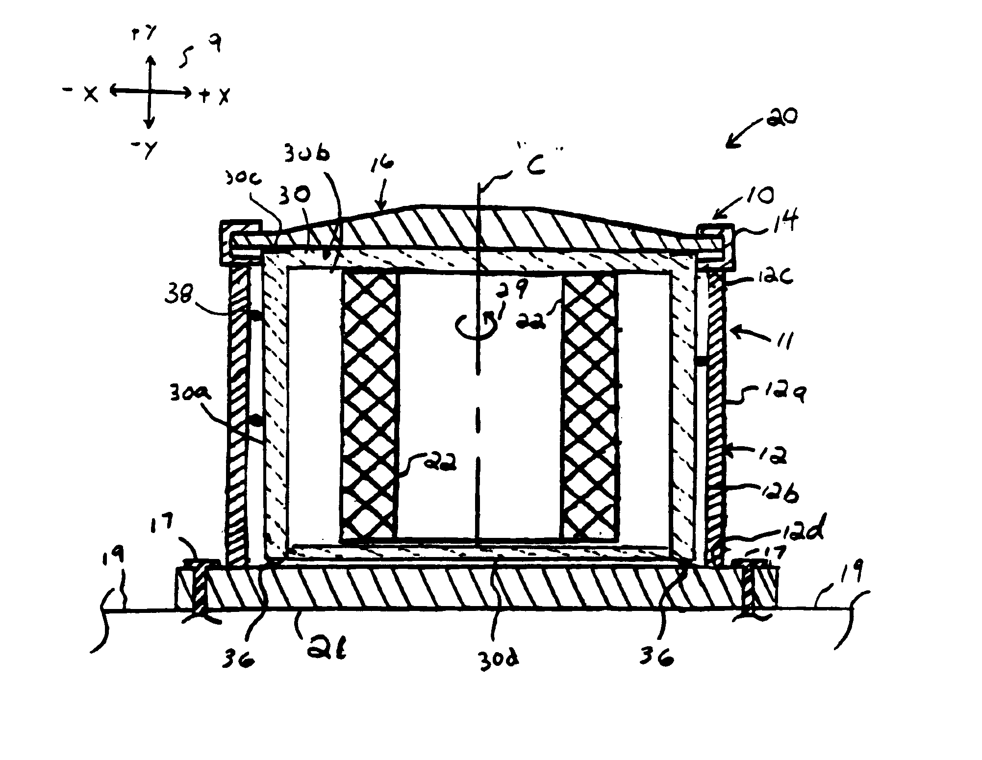
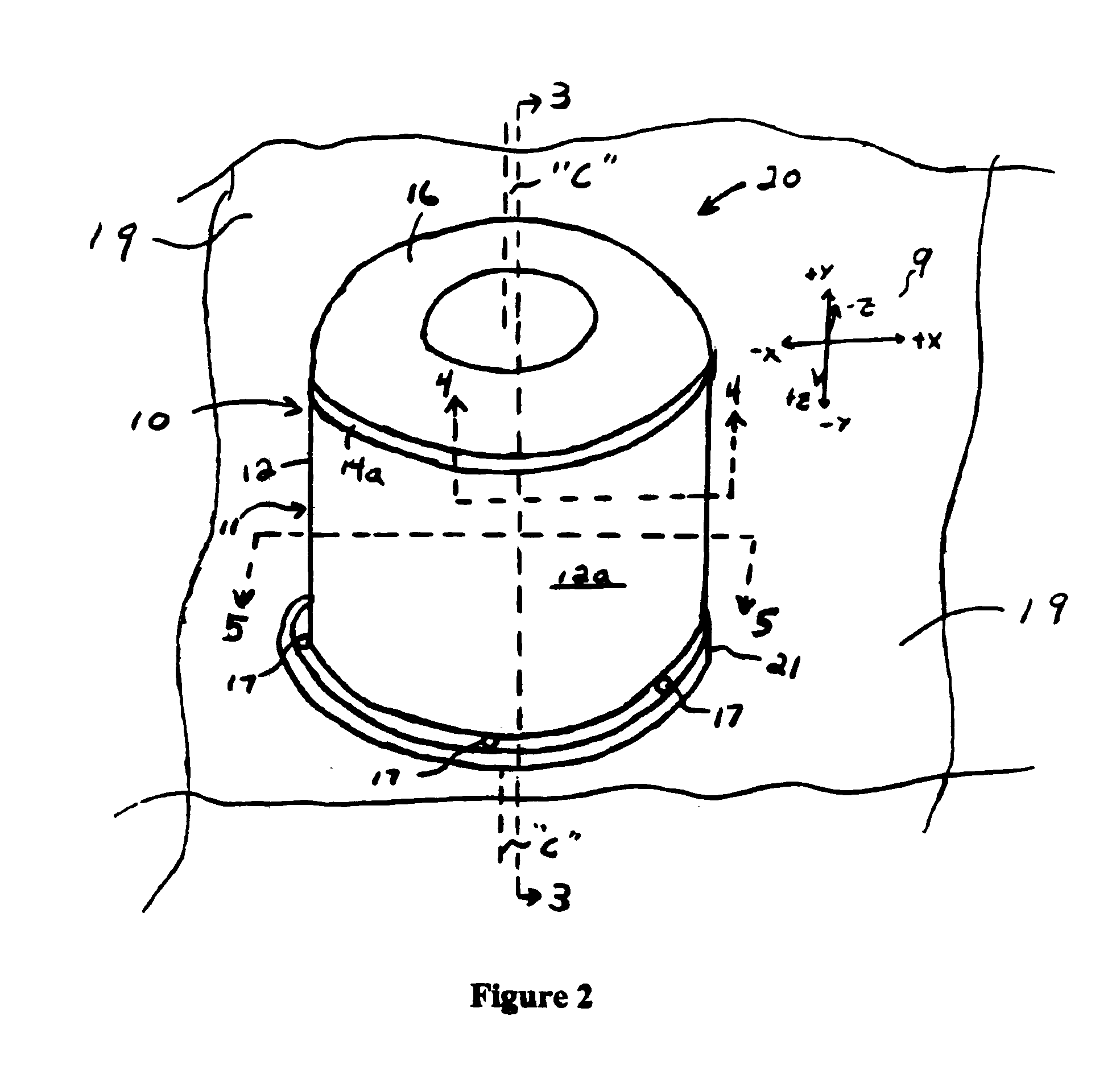
[0038]FIGS. 2-8 each depict a presently-preferred embodiment of an energy-absorbing housing system for a flywheel system. The figures are each referenced to a common coordinate system 9 depicted therein. The invention is described herein in connection with a flywheel system 20 comprising a flywheel 22. This particular embodiment is described for illustrative purposes only, and is not intended to limit the contemplated scope of the invention in any way. The present invention can be used in conjunction with virtually any type of mechanical system in which it is necessary or desirable to contain or de-energize debris resulting from the catastrophic failure of a rotating mass, as with, for example, high-speed centrifuges, centrifugal separators, rotary filling machines, and the like.

[0039]FIGS. 2 and 3 show an energy-absorbing housing system 10, generally. The energy-absorbing housing system 10 comprises a substantially cylindrical outer housing 11. The outer housing 11 is substantially...


PUM


Abstract

The invention provides a flywheel system with energy-absorbing housing. The system provides a novel liner and restraint ribs which serve to de-energize debris particles resulting from the catastrophic failure of a flywheel. Also provided are energy-absorbing housing systems comprising a rotatable liner, one or more restraint ribs, and a fluid film bearing to control and dissipate the energy from the failure of a rotating mass.

Description

[0001]This is a continuation of application Ser. No. 09 / 960,043, filed Sep. 22, 2001, now abandoned.FIELD OF THE INVENTION[0002]The present invention relates generally to flywheel systems. More particularly the invention relates to a high-speed flywheel system having an energy-absorbing housing for dissipating large forces resulting from the catastrophic structural failure of a flywheel system.BACKGROUND OF THE INVENTION[0003]The applied use of flywheels as a method of storing energy dates back to at least the use of potter's wheels. Modem flywheels are used as energy storage and power management devices. In essence, they couple a motor generator with a large-inertia rotor. Typical applications may include a vacuum enclosure or housing, friction-reducing elements such as magnetic bearings, coolant systems, sensors, charge / discharge circuitry, computer hardware and software for control. Flywheels systems can support industrial voltages.[0004]Flywheels can be designed for primary appl...

Claims


Application Information

Patent Timeline
IPC IPC(8): F16F15/315F16F15/30
CPCF16F15/315Y10T74/2119Y10T74/2121
Inventor GRISWOLD, RAY F.ZORZI, EDWARD S.
Owner AFS TRINITY POWER CORP
Why Eureka
Try Eureka