Lens processing management system

Inactive Publication Date: 2005-05-10
CANON KK
View PDF4 Cites 12 Cited by
  • Summary
  • Abstract
  • Description
  • Claims
  • Application Information

AI Technical Summary

Benefits of technology

[0016]Another object of the present invention is to construct lens processing management systems in which the quality in each process is stabilized and thereby the reliability of the quality management is improved.
[0017]Still another object of the present invention is to construct lens processing management systems in which loss of time in works is reduced and thereby the number of products per worker is made maximum.
[0018]Still another object of the present invention is to construct lens processing management systems in which the whole of a line is unitarily managed to forward an efficient production plan and thereby the stock in each process is made minimum.

Problems solved by technology

In the field of lens processing, however, no group management system for unitarily managing and controlling many processing machines and information on many “lines”, as in the field of plastic molding, have been known.
Further, although periodical checks (measurements) for each quality item being managed are carried out, there is a difficulty that the timings for carrying out the quality checks differ from item to item.
As described above, in the field of lens processing, because of the numerousness of items to be managed in each process and the presence of measurement and adjustment works that require skillfulness, such group management techniques as disclosed in the field of plastic molding could not be applied.
As described above, in the field of lens processing, manufacturers have not completely left production systems of long standing that rely upon experts, and a recent rise of labor cost is gradually weakening their competitive powers in cost.

Method used


Image

  • Lens processing management system
  • Lens processing management system
  • Lens processing management system

Examples


embodiment 1

[0050]Next, an embodiment of the present invention will be described specifically with reference to FIGS. 1 and 2.

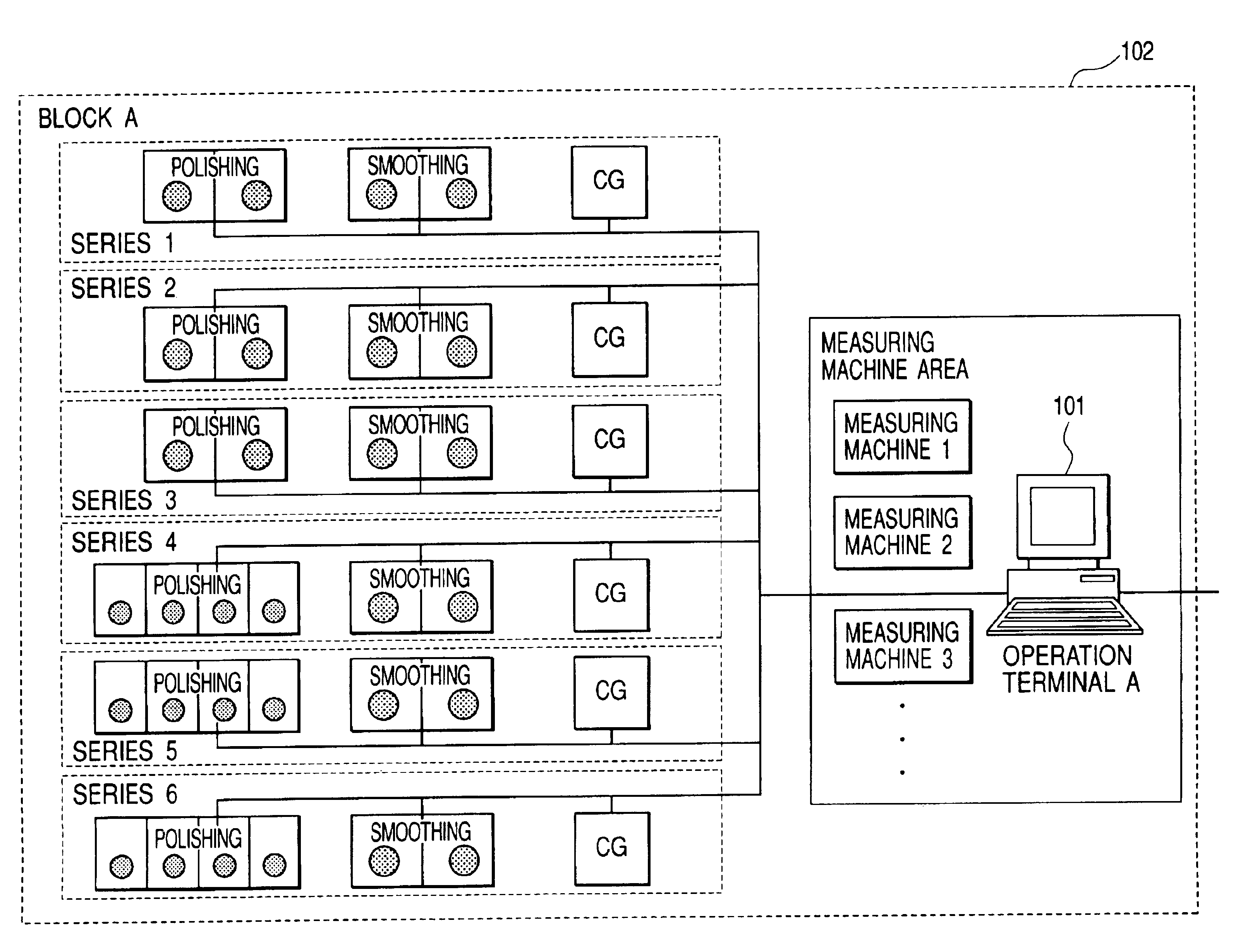
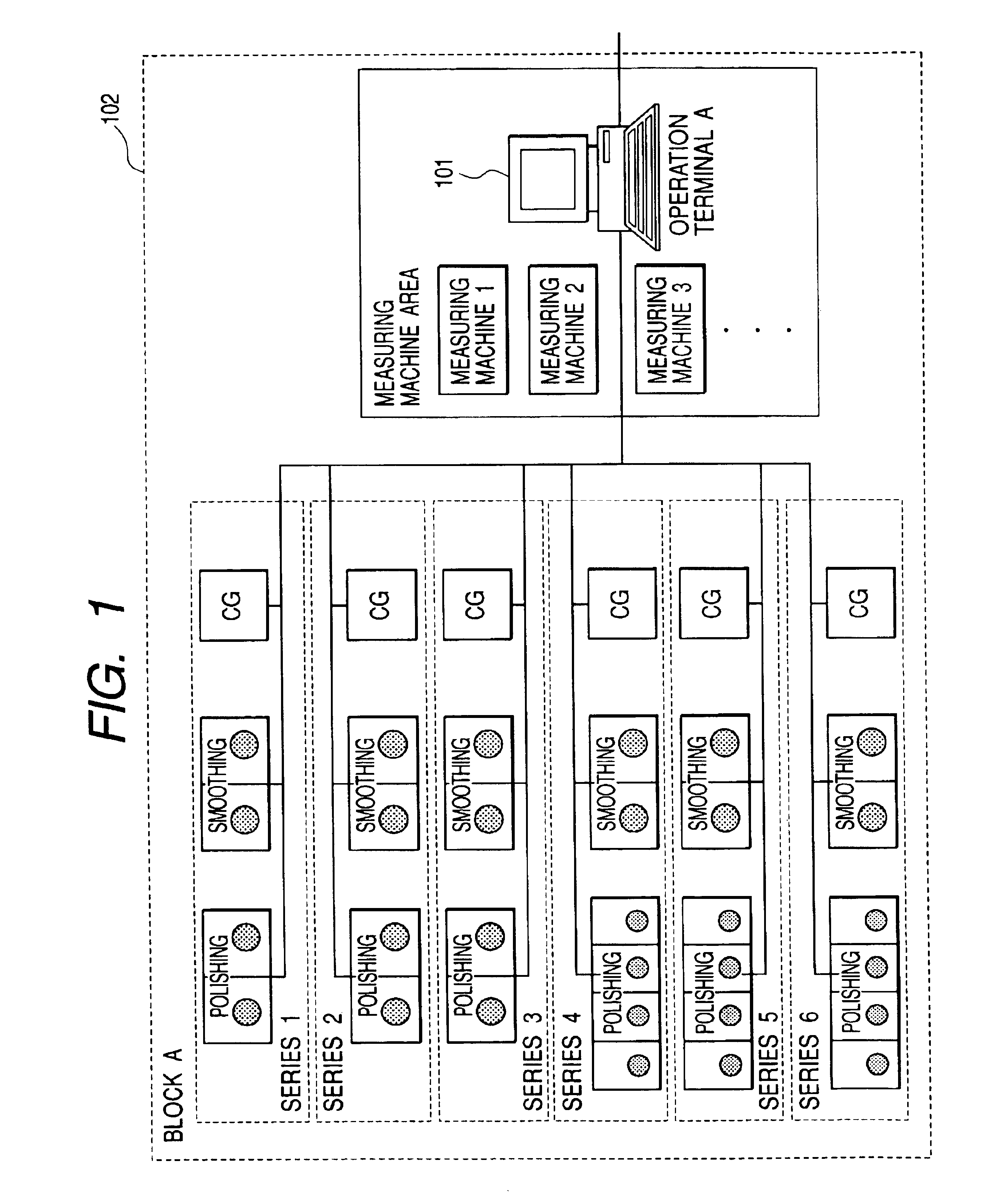
[0051]FIG. 1 illustrates a block 102 made up of an operation terminal A101 and a plurality of types of processing machines.

[0052]FIG. 1 shows a block for “single side finishing scheme” in which one side of each lens is finished and then the other side is finished. Each series comprises one rough grinding machine (CG machine), one smoothing machine (2-spindle machine), and one polishing machine (2- or 4-spindle machine). These series are managed in a database within a server computer, alternatively they may be managed by each operation terminal A101.

[0053]Only one side of each lens is processed in one series, so each lens passes through two series and then it is sent to the subsequent process.

[0054]Each processing machine in the block 102 is provided with a controller connectable to a LAN (Local Area Network). The controller can rewrite setting conditions such as automati...

embodiment 2

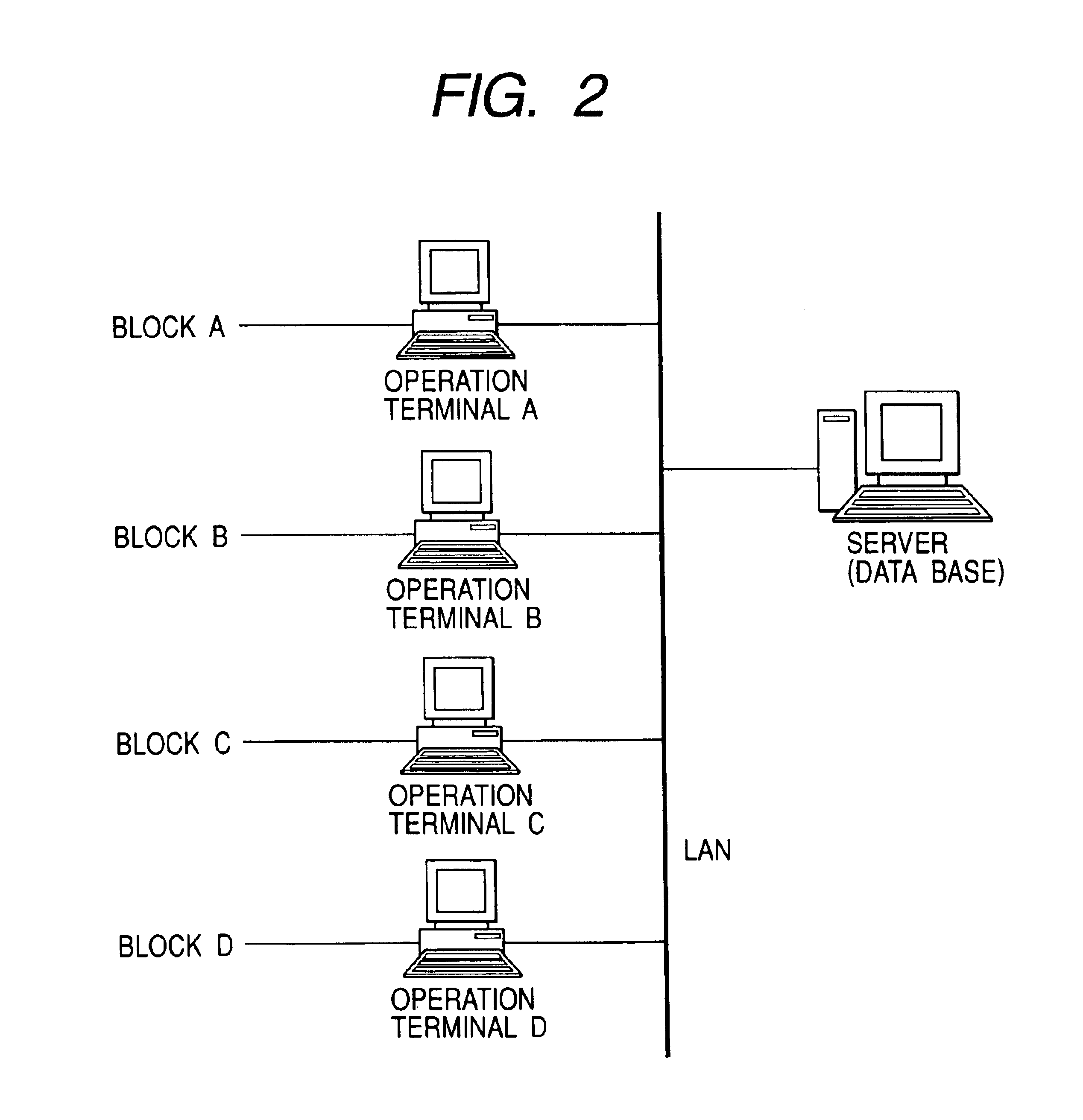
[0140]In the lens processing management system of Embodiment 1, the server computer is connected with operation terminals and data of quality history and series information, etc., are unitarily managed in a database within the server computer. However, it is also possible to provide a similar database in each operation terminal.

[0141]In that case, each operation terminal (each block) has a database for quality history, series information, etc. And, each operation terminal refers to data in its own database to calculate the optimum processing machine setting every series unit. Therefore, differently from Embodiment 1, each operation terminal need not access the server computer when calculating the optimum processing machine setting.

[0142]In this construction, since each operation terminal (each block) has its own database, the server computer is unneedful when each operation terminal calculates the optimum processing machine setting. But, for unitarily managing the databases of the o...

embodiment 3

[0143]In Embodiments 1 and 2, the construction and role of the whole of the lens processing system have been described. In Embodiment 3, functions specific to this system will be described further.

[0144]The classification of series in Embodiment 2 is K-1 type of FIG. 4, in which a single side is finished with one spindle of rough grinding, two smoothing processes× one spindle, and one polishing process× two spindles.

[0145]FIG. 7 illustrates a bar graph displayed on a terminal screen to show the numbers of works in the rough grinding, smoothing, and polishing machines in one series in a given block.

[0146]In this graph, data shown by “after check” and “after tool change” indicate the differences between the currently counted value of the number of works in each processing machine, read out by an operation terminal, and the history data of the counted values of the number of works in the processing machine at the last quality check and at the last tool change in each process, read out ...


PUM

PropertyMeasurementUnit
Shapeaaaaaaaaaa
Processing propertiesaaaaaaaaaa

Abstract

The invention relates to management systems for unitarily managing and controlling information of a plurality of types of lens processing machines for manufacturing a glass lens of predetermined shape from a grass material. Its object is to construct production systems relying upon no experts, improve the reliability of quality management, make the products per worker the maximum, and make the stock in each process the minimum. To achieve this object, in a lens processing system comprising the plurality of types of processing machines for lens processing and an operation terminal connected with the processing machines through a network and capable of changing the settings of the processing machines, the operation terminal or a server unitarily manages various data every series unit and calculates the optimum settings for the processing machines every series unit.

Description

BACKGROUND OF THE INVENTION[0001]1. Field of the Invention[0002]The present invention relates to a lens processing management system, particularly, a lens processing management system for unitarily managing and controlling a plurality of types of processing machines included in a lens manufacture line and information in the line.[0003]2. Related Background Art[0004]Conventionally, so-called group management systems for unitarily managing and controlling various processing machines have been proposed. For example, systems for group management of injection molding machines used for plastic molding have been devised, which are disclosed in Japanese Patent No. 2543793, etc.[0005]On the other hand, in the field of lens processing, as disclosed in Japanese Patent Application Laid-Open No. 06-315849, etc., in certain partial fields, systems have been used in which a processing system and a measuring system are connected with each other through a LAN (Local Area Network), and an operation p...

Claims


Application Information

Patent Timeline
IPC IPC(8): B24B13/00B24B13/06B24B51/00
CPCB24B13/0037B24B51/00B24B13/06
Inventor KOZAKAI, TAKASHISHINOHARA, IZURU
Owner CANON KK
Why Eureka
Try Eureka