Deposition methods

Inactive Publication Date: 2005-05-10
ROUND ROCK RES LLC
View PDF58 Cites 240 Cited by
  • Summary
  • Abstract
  • Description
  • Claims
  • Application Information

AI Technical Summary

Benefits of technology

[0009]In one implementation, a deposition method includes positioning a substrate within a deposition chamber defined at least in part by chamber walls. At least one of the chamber walls comprises a chamber surface having a plurality of purge gas inlets to the chamber therein. A process gas is provided over the substrate effective to d

Problems solved by technology

This is particularly problematic in ALD and other CVD processes, yet can also occur with PVD chambers.
Where there is a great degree of varying topography and/or there are high aspect ratio features on the substrate, it can be difficult to move the unreacted gases or reaction by-products from deep within openings for ultimate removal from the chamber.
Further, certain reaction by-products, particularly intermediate reaction by-products, may not be gaseous and may not completely react to form gaseous reaction by-products in the typical short precursor pulse times. Accordingly, the purge gas pulse may not be effec

Method used


Image

  • Deposition methods
  • Deposition methods
  • Deposition methods

Examples


Embodiment Construction

[0019]This disclosure of the invention is submitted in furtherance of the constitutional purposes of the U.S. Patent Laws “to promote the progress of science and useful arts” (Article 1, Section 8).

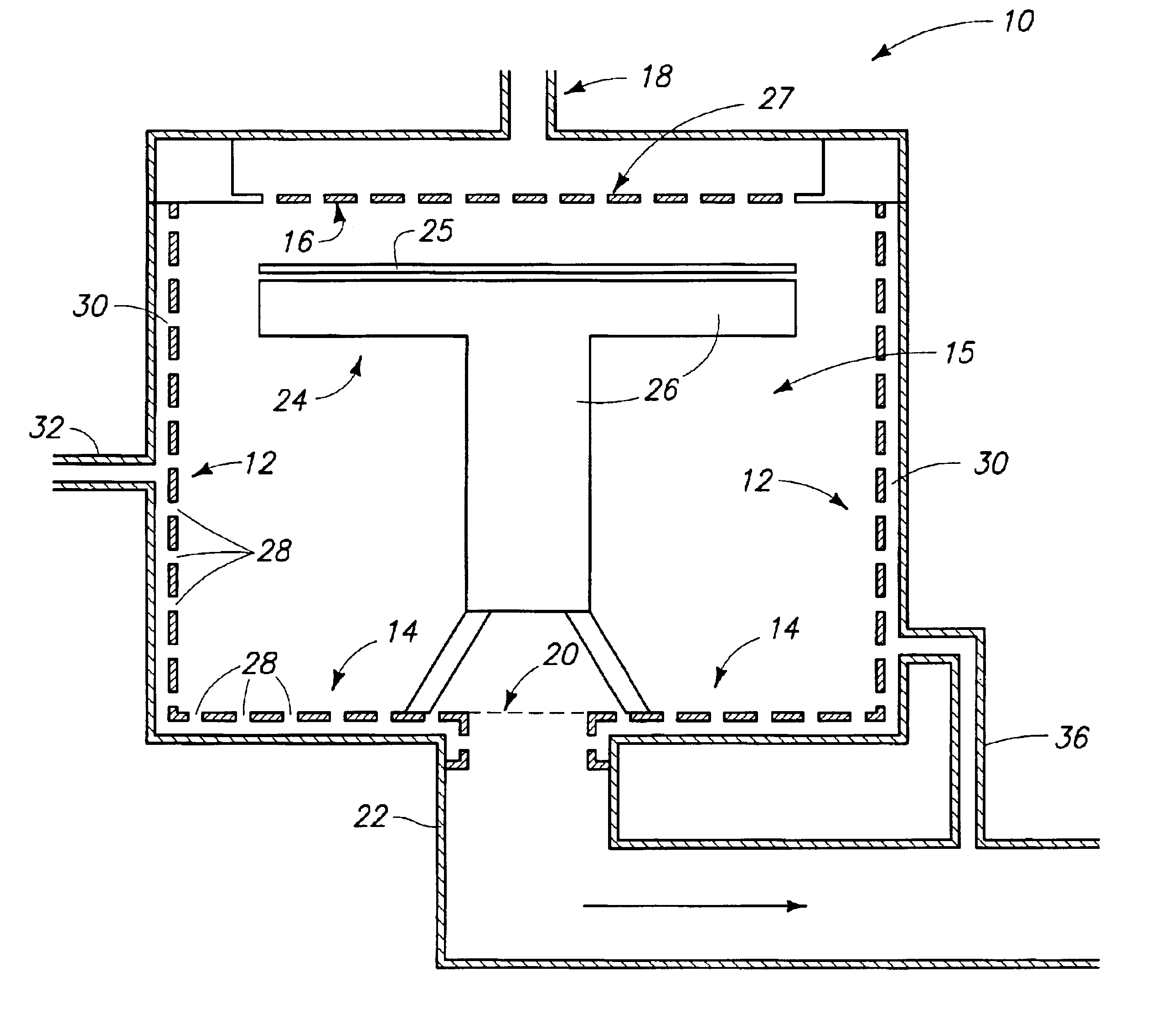
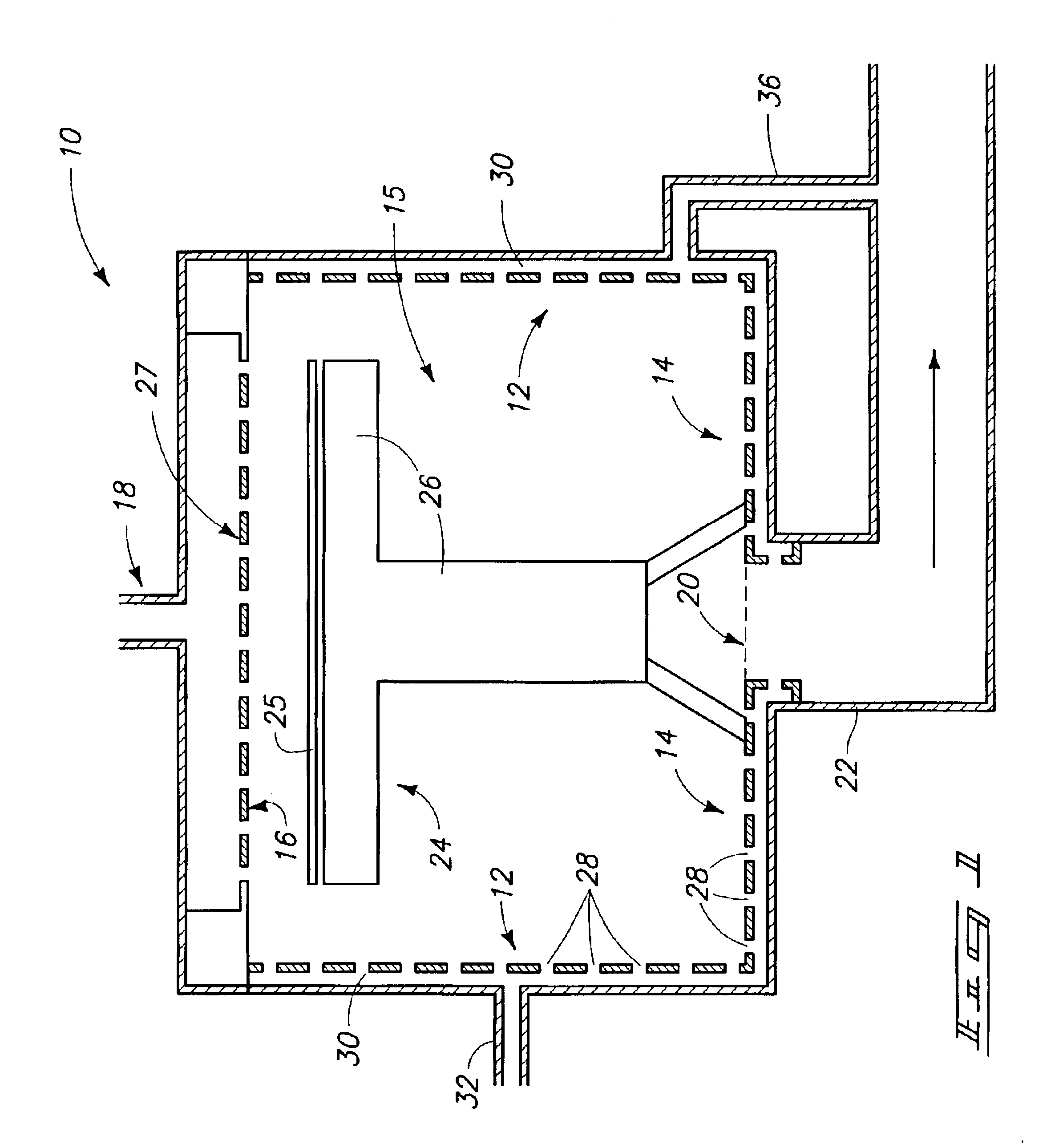
[0020]By way of example only, FIG. 1 depicts an exemplary embodiment chemical vapor deposition apparatus 10 usable in accordance with methodical aspects of the invention. Any other apparatus, whether existing or yet-to-be-developed, could of course also / alternatively be utilized. Apparatus 10 includes a chamber 15 defined at least in part by chamber walls 12, 14 and 16. Wall or walls 12 comprise a chamber sidewall, wall or walls 14 comprise a chamber base wall, and wall or walls 16 comprise a chamber top wall. Chamber 15 includes at least one process chemical inlet 18 thereto, and an outlet 20 feeding therefrom. Outlet 20 feeds to a foreline 22 for connection with a vacuum pump (not shown). A suitable substrate holder 24 is provided within chamber 15. Such includes some suitable support s...


PUM

PropertyMeasurementUnit
Volumeaaaaaaaaaa
Plasma poweraaaaaaaaaa

Abstract

A deposition method includes positioning a substrate within a deposition chamber defined at least in part by chamber walls. At least one of the chamber walls comprises a chamber surface having a plurality of purge gas inlets to the chamber therein. A process gas is provided over the substrate effective to deposit a layer onto the substrate. During such providing, a material adheres to the chamber surface. Reactive purge gas is emitted to the deposition chamber from the purge gas inlets effective to form a reactive gas curtain over the chamber surface and away from the substrate, with such reactive gas reacting with such adhering material. Further implementations are contemplated.

Description

TECHNICAL FIELD[0001]This invention relates to deposition methods.BACKGROUND OF THE INVENTION[0002]Semiconductor processing in the fabrication of integrated circuitry typically includes the deposition of layers on semiconductor substrates. Exemplary processes include physical vapor deposition (PVD), and chemical vapor deposition (CVD) which herein includes atomic layer deposition (ALD). With typical ALD, successive mono-atomic layers are adsorbed to a substrate and / or reacted with the outer layer on the substrate, typically by successive feeding of different precursors to the substrate surface.[0003]Chemical and physical vapor depositions are typically conducted within chambers or reactors which retain a single substrate upon a wafer holder or susceptor. The chambers include internal walls and other internal components which can undesirably have deposition product deposited thereupon in addition to the substrate. This is particularly problematic in ALD and other CVD processes, yet c...

Claims


Application Information

Patent Timeline
IPC IPC(8): C23C16/44C23C16/455
CPCC23C16/4401C23C16/45519C23C16/455
Inventor SARIGIANNIS, DEMETRIUSDERDERIAN, GARO J.BASCERI, CEMSANDHU, GURTEJ S.GEALY, F. DANIELCARLSON, CHRIS M.
Owner ROUND ROCK RES LLC
Why Eureka
Try Eureka