Magnetostrictive actuator

a magnetic field and actuator technology, applied in the direction of generator/motor, device details, transducer diaphragms, etc., can solve the problems of inability to generate the necessary magnetic field to cause the change in length of the giant magnetostrictive material (gmm) and previously been impractical for portable domestic use, and achieve the effect of improving the acoustic coupling, small size and weight, and small current consumption

Inactive Publication Date: 2005-05-10
NEWLANDS TECH
View PDF4 Cites 15 Cited by
  • Summary
  • Abstract
  • Description
  • Claims
  • Application Information

AI Technical Summary

Benefits of technology

[0008]The body of the actuator is formed of a non-magnetic material, for example a zinc alloy, rather than steel, as in conventional magnetostrictive actuators. Thus, a magnetic return path is not provided, and it has been found that this also helps to enhance the linearity of the magnetic field through the GMM.
[0049]The means for supplying the audio frequency signal may be a link to a separate radio communications device, or it may comprise a radio incorporated into the helmet. Such a helmet may be useful for fire fighters, permitting messages to be heard clearly in adverse conditions, since the helmet radiates sound around the head, permitting it to be heard without blocking out, or being blocked out by, ambient sound.

Problems solved by technology

Magnetostrictive devices can generate a substantial force at a relatively low voltage, but have previously been impractical for portable domestic uses for two reasons.
Firstly, the current consumption to generate the necessary magnetic fields to cause change in length of the giant magnetostrictive material (GMM) is relatively high, and secondly, the cost of the GMM would be prohibitive.
It has been found that simply scaling down conventional magnetostrictive actuators does not produce satisfactory audio output, with high levels of distortion or very low volume.

Method used


Image

  • Magnetostrictive actuator
  • Magnetostrictive actuator
  • Magnetostrictive actuator

Examples


Embodiment Construction

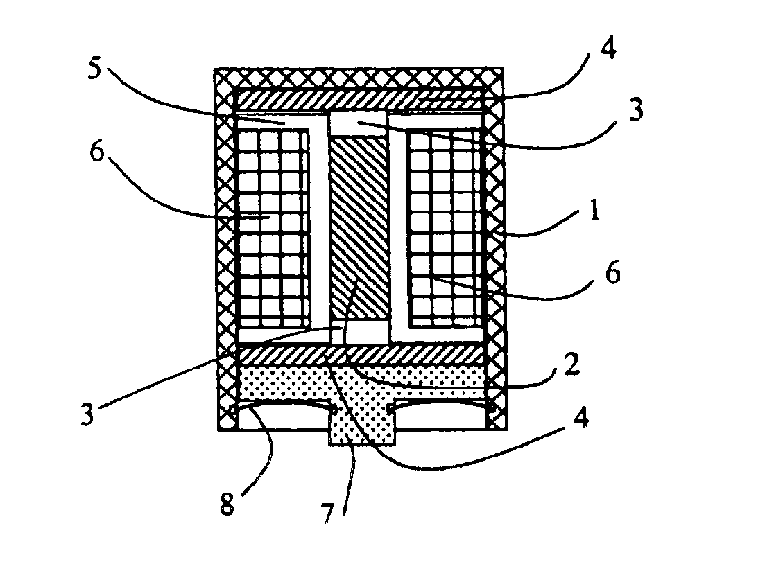
[0065]The magnetostrictive actuator shown in FIG. 1 comprises a casing 1, for example of a non-magnetic material, in which is located a rod 2 of giant magnetostrictive material (which for convenience may comprise two pieces of the GMM, end-to-end), with a non-magnetic spacer 3, for example of aluminium or a ceramic material capable of transmitting force, disposed at each end thereof to space the GMM rod 2 from a pair of disc magnets 4 of substantially greater diameter than the width of the rod. A plastics core 5 serves to locate and hold the GMM rod 2 and spacers, and carries an electromagnetic winding 6 which is connected via wires (not shown) to a separate energising signal source. A foot 7 transmits the force produced by the actuator to the desired location. A spring clip 8 held in grooves around the inside of the casing 1 and the foot 7 holds the assembly together and imposes a mechanical pre-stress on the GMM rod 2.

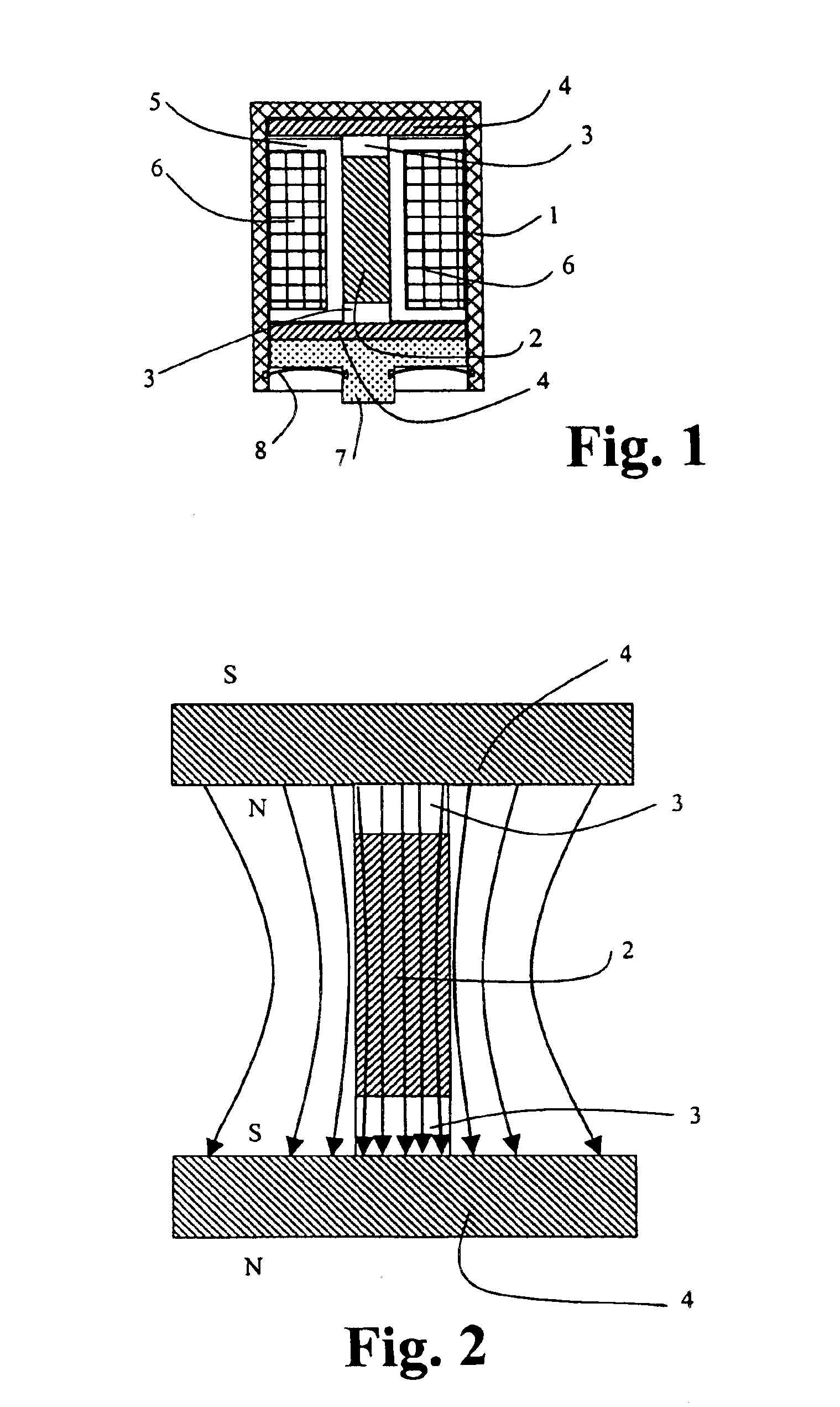
[0066]As may be seen more clearly from FIG. 2, by selecting dis...


PUM


Abstract

A magnetostrictive actuator comprises a rod of giant magnetostrictive material, biasing permanent magnets arranged at each end thereof and coaxially therewith so as to pass a magnetic field through the rod. An energizing electromagnetic coil is connected to an energizer so as to superimpose on the magnetic field passing through the rod an alternating magnetic field to cause variation in the length of the rod in response thereto. The permanent magnets are each in the form of a disc having a cross-sectional area substantially greater than that of the rod and are spaced from the ends of the rods by material of low magnetic permeability. The magnetic field in the rod is thereby substantially linear along the length thereof.

Description

[0001]This application is a continuation of co-pending U.S. patent application Ser. No. 10 / 472,718, filed on Sep. 19, 2003, which is a 371 of PCT / GB02 / 01111, filed Mar. 19, 2002.FIELD OF THE INVENTION[0002]This invention relates to a magnetostrictive actuator especially suitable for audiofrequency use and to audio output and communication devices which may employ such an actuator.BACKGROUND TO THE INVENTION[0003]It is known that a panel may be made to function as a loudspeaker by attaching to the panel an audiofrequency actuator which can transmit acoustic signals into the panel. WO92 / 03024 discloses one such panel. WO98 / 52289 suggests the use of standard trim panels in a motor vehicle as a means of radiating the output of a radio, tape player or the like, listing magnetostrictive, electromagnetic, electrostatic and micromotor transducers as possible for the job, although preferring piezoelectric transducers.[0004]While such panels can be made to operate as satisfactory loudspeakers...

Claims


Application Information

Patent Timeline
Patent Type & Authority Patents(United States)
IPC IPC(8): H04R23/00H04R15/00H01L41/12
CPCH04R23/00H04R15/00H04R2460/13H04R11/02H04R7/045H10N35/00
Inventor FLANAGAN, GRAHAMMETHERINGHAM, WILLIAM JOHNJOHNSON, DAVIDSMITH, BRIAN DOUGLAS
Owner NEWLANDS TECH
Why Eureka
Try Eureka