Electromagnetic coupling connector for three-dimensional electronic circuits

a technology of electronic circuits and coupling connectors, applied in the direction of one-port networks, multi-port networks, waveguide type devices, etc., can solve the problems of inability to easily integrate conventional connectors into stacked, or three-dimensional, electronic systems to provide communication between the various layers, and the inability of conventional connectors to be easily integrated into three-dimensional circuits

Inactive Publication Date: 2005-05-10
MASSACHUSETTS INST OF TECH
View PDF15 Cites 44 Cited by
  • Summary
  • Abstract
  • Description
  • Claims
  • Application Information

AI Technical Summary

Problems solved by technology

Conventional connectors are often inadequate for high-density electronic systems.
In particular, conventional connectors cannot readily be integrated into stacked, or three-dimensional, electronic systems to provide communication between the various layers.
Particularly challenging are three-dimensional circuits in which boards, or layers, of the electronics structure require replacement or repair.
The pins are often bent during assembly and do no make proper electrical connections.
Furthermore, the thickness (or diameter) of the pins cannot be decreased without adversely affecting durability.
Consequently, the connection density is limited.
PGA and LGA connectors generally exhibit wear with repeated insertion and removal, and are susceptible to dust and corrosion.
The connected items cannot be reliably separated once the solder process is completed.
Moreover, the solder balls are subject to stress due to thermal expansion and shrinking, and the connections can fail over time.
Optical connectors generally are not acceptable for high-density connections due to their inherent cost and power consumption.

Method used


Image

  • Electromagnetic coupling connector for three-dimensional electronic circuits
  • Electromagnetic coupling connector for three-dimensional electronic circuits
  • Electromagnetic coupling connector for three-dimensional electronic circuits

Examples


Embodiment Construction

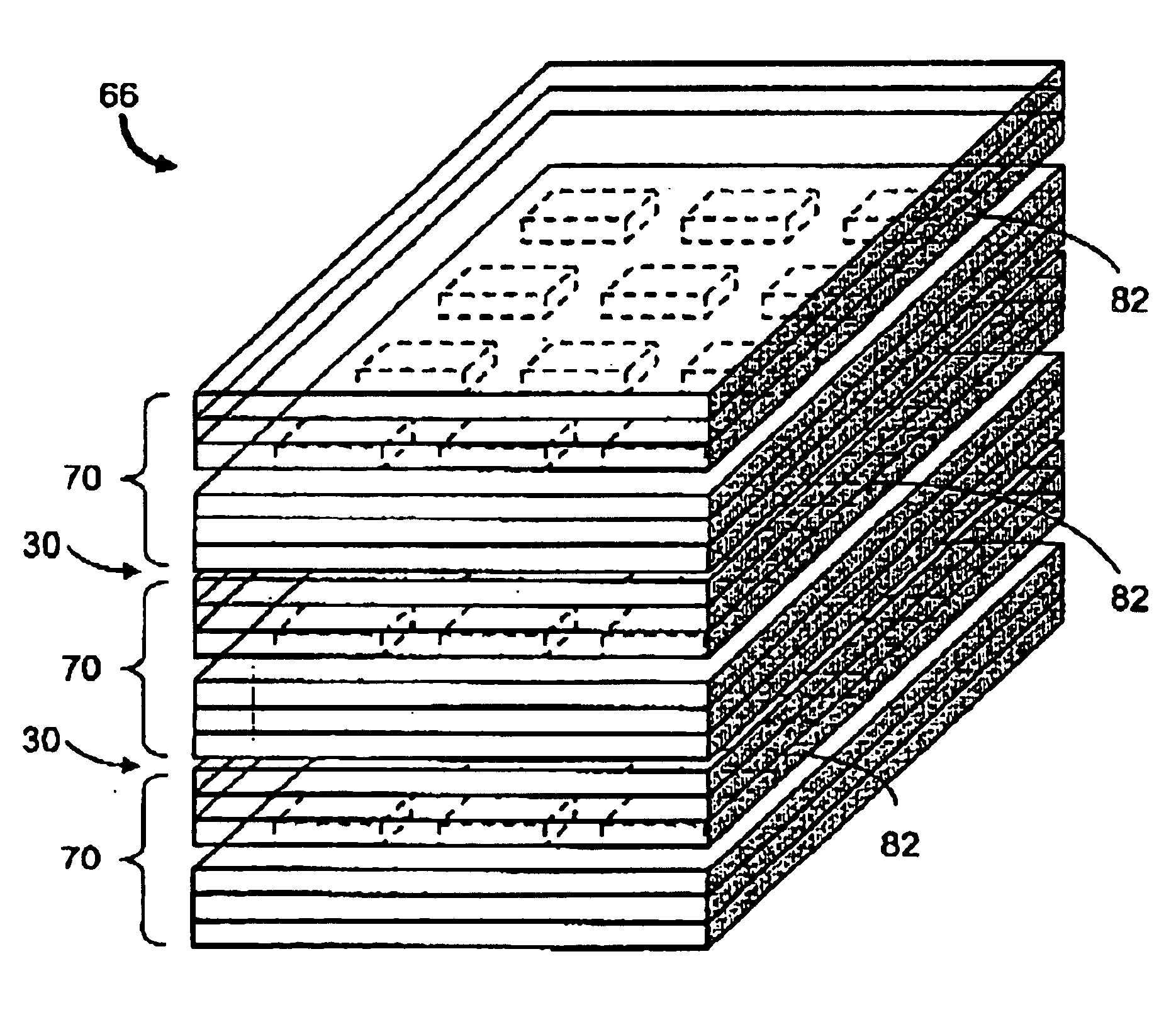
[0024]In brief overview, the present invention relates to a reliable high-density, low-cost electromagnetic coupling connector that can be connected and disconnected many times. The coupling connector is resistant to wear, corrosion, dust and repeated thermal stress. The coupling connector can operate with a mating coupling connector across a small gap. Alternatively, the coupling connector can operate while in contact with the mated coupling connector. Multiple coupling connectors can be used to couple vertically stacked circuit layers, including layers having analog and digital processing modules.

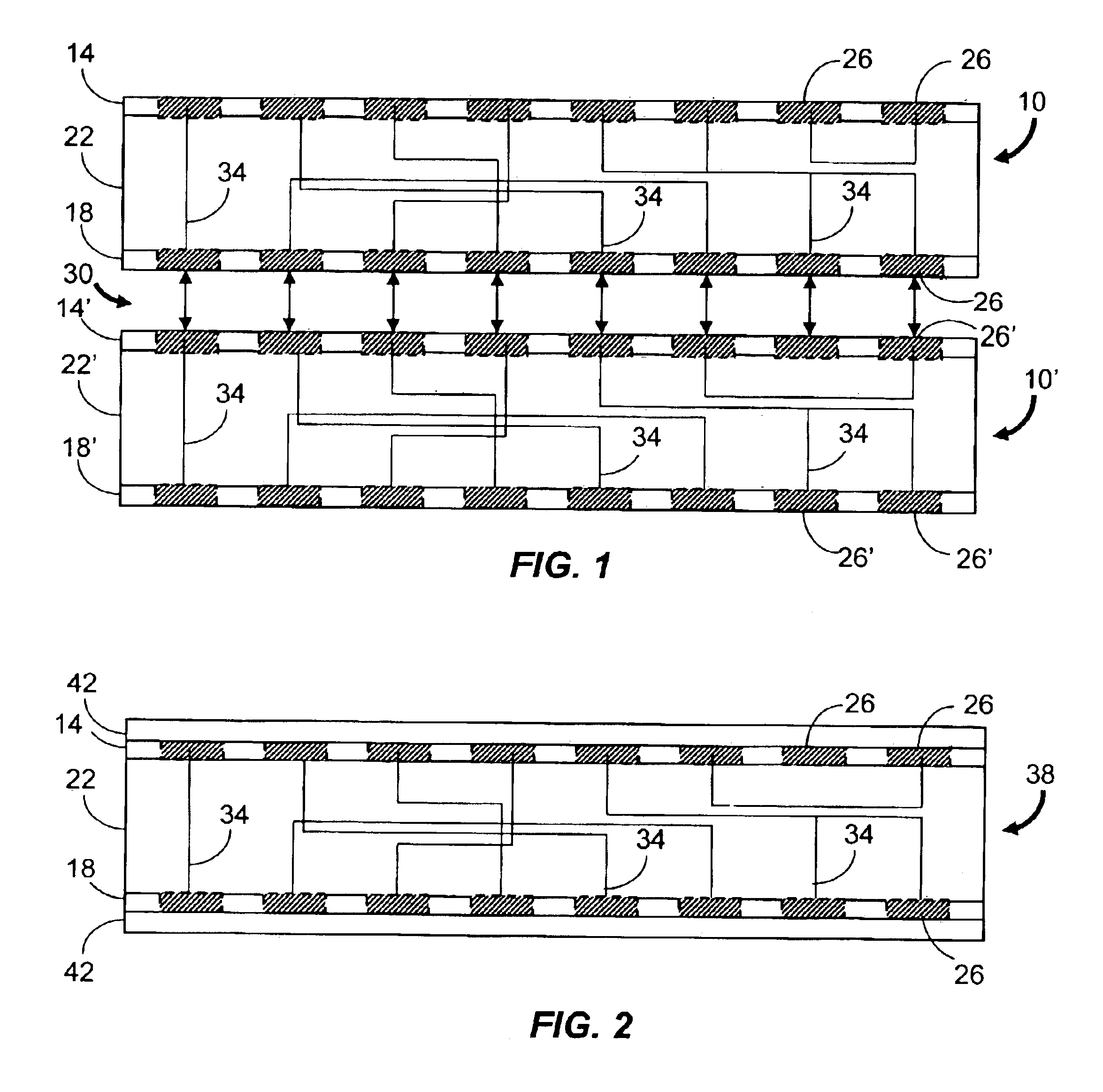
[0025]FIG. 1 depicts a pair of three-dimensional coupling connectors 10 and 10′ according to the present invention. The connectors 10, 10′ are shown coupled to one another for transmitting and receiving data signals by electromagnetic communication. Primed references are used to identify components of coupling connector 10′ that are similar to their unprimed counterparts in coupling conne...


PUM


Abstract

An electromagnetic coupling connector for three-dimensional electronic circuits is described. The coupling connector includes two coupling layers each having multiple electromagnetic coupling elements. Each coupling element can communicate through an electromagnetic path to a mating coupling element in a separate coupling connector. A routing layer is disposed between the two coupling layers and conducts an electrical signal between a coupling in one layer and at least one coupling element in the other layer. The coupling connector can also include a device layer having devices such as analog processors, memory modules and switching processor modules.

Description

CROSS-REFERENCE TO RELATED APPLICATIONS[0001]This application claims the benefit of provisional U.S. patent application Ser. No. 60 / 395,456, filed Jul. 12, 2002, titled “Electro-Magnetic Coupling Connectors,” the entirety of which provisional application is incorporated by reference herein.GOVERNMENT RIGHTS IN THE INVENTION[0002]This invention was made with United States government support under Contract No. F19628-00-C-0002 awarded by the United States Air Force. The government may have certain rights in the invention.FIELD OF THE INVENTION[0003]The invention relates generally to an electromagnetic coupling connector for three-dimensional electronic circuits. More particularly, the invention relates to a coupling connector having layers of coupling elements for communication to mating coupling elements in an adjacent coupling connector through electromagnetic paths.BACKGROUND[0004]Various types of electrical connectors are used in analog and digital electronic systems to enable com...

Claims


Application Information

Patent Timeline
Patent Type & Authority Patents(United States)
IPC IPC(8): H01P5/16H01P5/18
CPCH01L23/48H01L25/0652H01P5/187H01L2225/06527H01L2225/06589H01L2924/3011H01L2924/0002H01L2924/00
Inventor SONG, WILLIAM S.
Owner MASSACHUSETTS INST OF TECH
Why Eureka
Try Eureka