Protected exciter for an electrical power generator and associated methods

Inactive Publication Date: 2005-05-10
SIEMENS ENERGY INC
View PDF19 Cites 11 Cited by
  • Summary
  • Abstract
  • Description
  • Claims
  • Application Information

AI Technical Summary

Benefits of technology

[0010]With the foregoing background in mind, it is therefore an object of the present invention to provi

Problems solved by technology

A common problem associated with conventional rectifying circuits is commutation voltage spikes.
The reverse recovery current can damage the semiconductor switching device.
Moreover, were such damage to cause a diode failure, a phase-to-phase fault could result in destructively high currents within the armature windings.
This danger is particularly acute in large-scale electrical generators in which high power density brushless exciters are typically used.
Such circuits can be costly to produce and take up space within an electrical generator while adding weight to the exciter.
One problem with such a device is that the saturable r

Method used


Image

  • Protected exciter for an electrical power generator and associated methods
  • Protected exciter for an electrical power generator and associated methods
  • Protected exciter for an electrical power generator and associated methods

Examples


Embodiment Construction

[0025]The present invention will now be described more fully hereinafter with reference to the accompanying drawings that illustrate preferred embodiments of the invention. This invention may, however, be embodied in many different forms and should not be construed as limited to the embodiments set forth herein. Rather, these embodiments are provided so that this disclosure will be thorough and complete, and will fully convey the scope of the invention to those skilled in the art. Like numbers refer to like elements throughout.

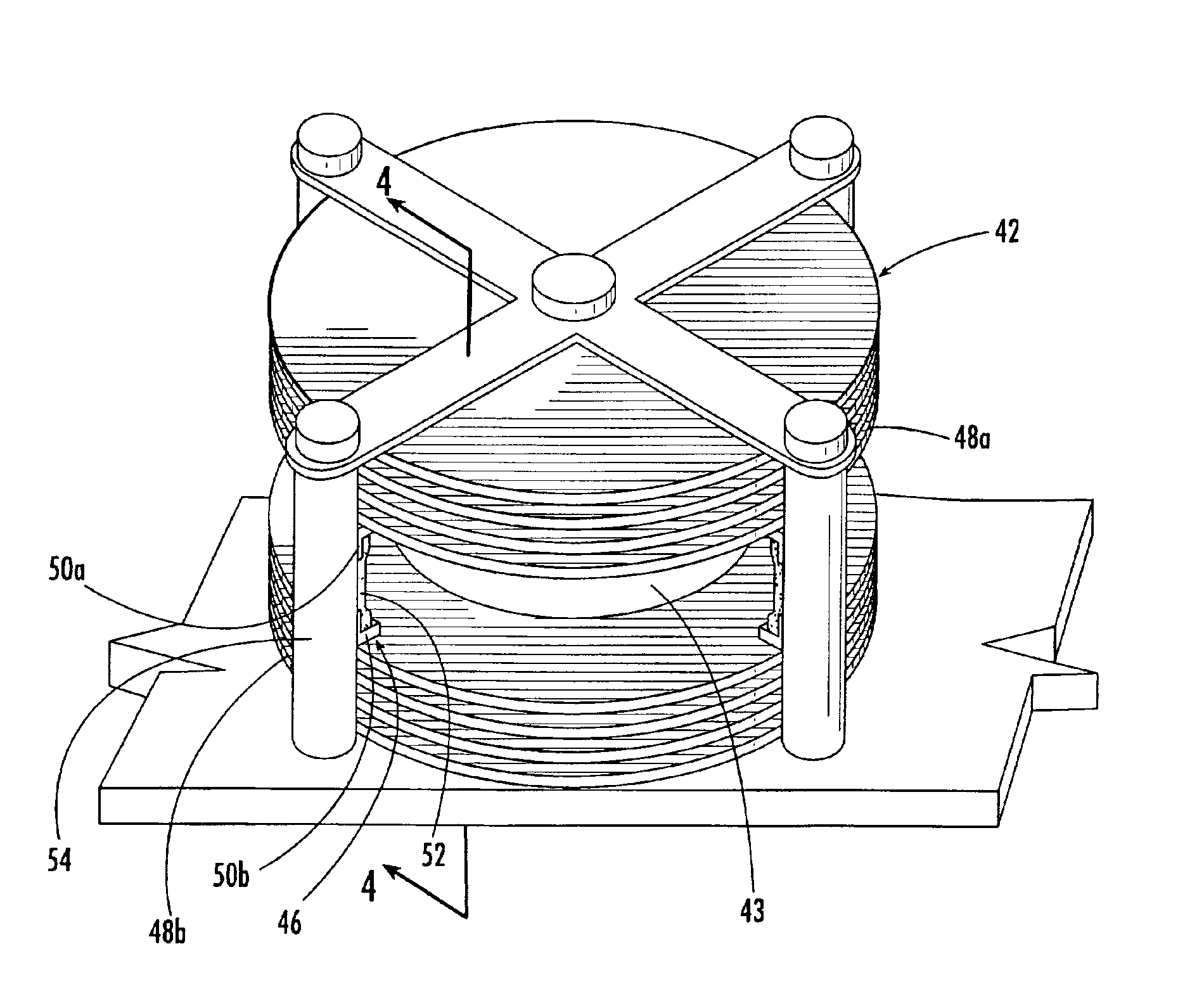
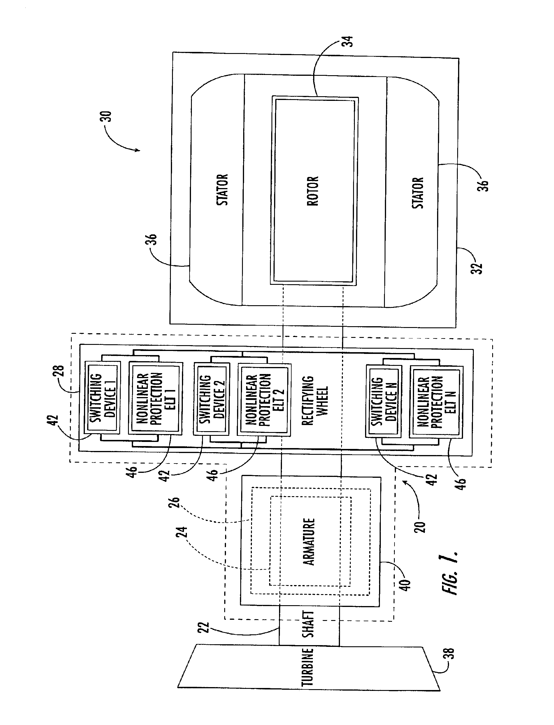
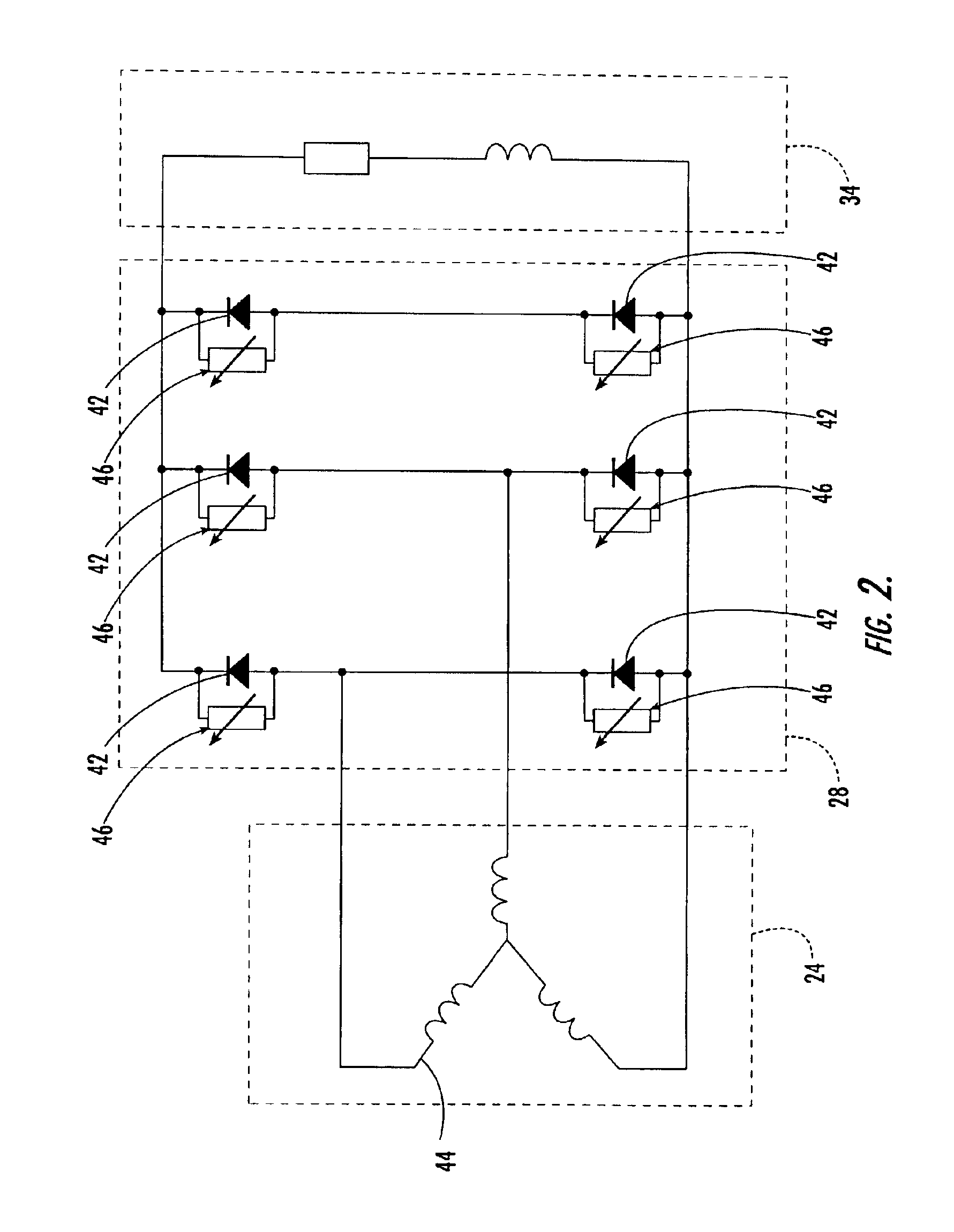
[0026]Referring initially to FIGS. 1 and 2, an exciter 20 according to the present invention is described in the context of an electrical generator 30 in which the exciter can be used. The exciter 20 illustratively includes a shaft 22, an armature 24 connected to the shaft, a field 26 surrounding the armature, and a rectifying wheel 28 connected to the shaft. The electrical generator 30 comprises a generator housing 32, a rotor 34 within the housing and connec...


PUM


Abstract

An exciter for an electrical power generator includes a shaft, an armature connected to the shaft, a field surrounding the armature to cause the armature to generate an alternating current, and a rectifying wheel The rectifying wheel includes a plurality of semiconductor switching devices connected to the rectifying wheel and arranged in a bridge configuration for rectifying the alternating current from the field. A respective non-linear protection device is connected in parallel with each of the semiconductor switching devices.

Description

FIELD OF THE INVENTION[0001]The present invention relates to the field of power generation and, more particularly, to an exciter for an electrical generator and associated methods.BACKGROUND OF THE INVENTION[0002]A power generator typically includes a stator, a rotor that turns within the stator to generate electrical power, and a mechanically driven shaft to turn the rotor within the stator. The rotor includes a field winding, to which an exciter current is supplied in generating electrical power. The exciter current typically is supplied with an exciter.[0003]The exciter itself can be an alternating current generator driven by the same source (e.g., steam-powered turbine) as the rotor and feeding the direct current to the field winding of the rotor via brushes and slip-rings. Increasingly, however, “brushless” exciters are being used in electrical generators. With a brushless exciter, the DC current is derived from an alternating current. The alternating current is generated in th...

Claims


Application Information

Patent Timeline
IPC IPC(8): H01L25/11H01L25/10H02H7/06H02M7/00H02K11/04H02P9/30
CPCH01L25/117H02P9/302H02K11/042H02M7/003H02H7/065H01L2924/3011H01L2924/0002
Inventor LEONOV, VLADIMIR
Owner SIEMENS ENERGY INC
Why Eureka
Try Eureka