
Microscope

Active Publication Date: 2011-04-21
CARL ZEISS MICROSCOPY GMBH
View PDF3 Cites 0 Cited by
  • Summary
  • Abstract
  • Description
  • Claims
  • Application Information

AI Technical Summary

Benefits of technology

[0010]It is the object of the invention to provide an improved microscope of the type mentioned above in which detectors can be efficiently protected from excessively high light outputs and which can be produced and used at lower cost.
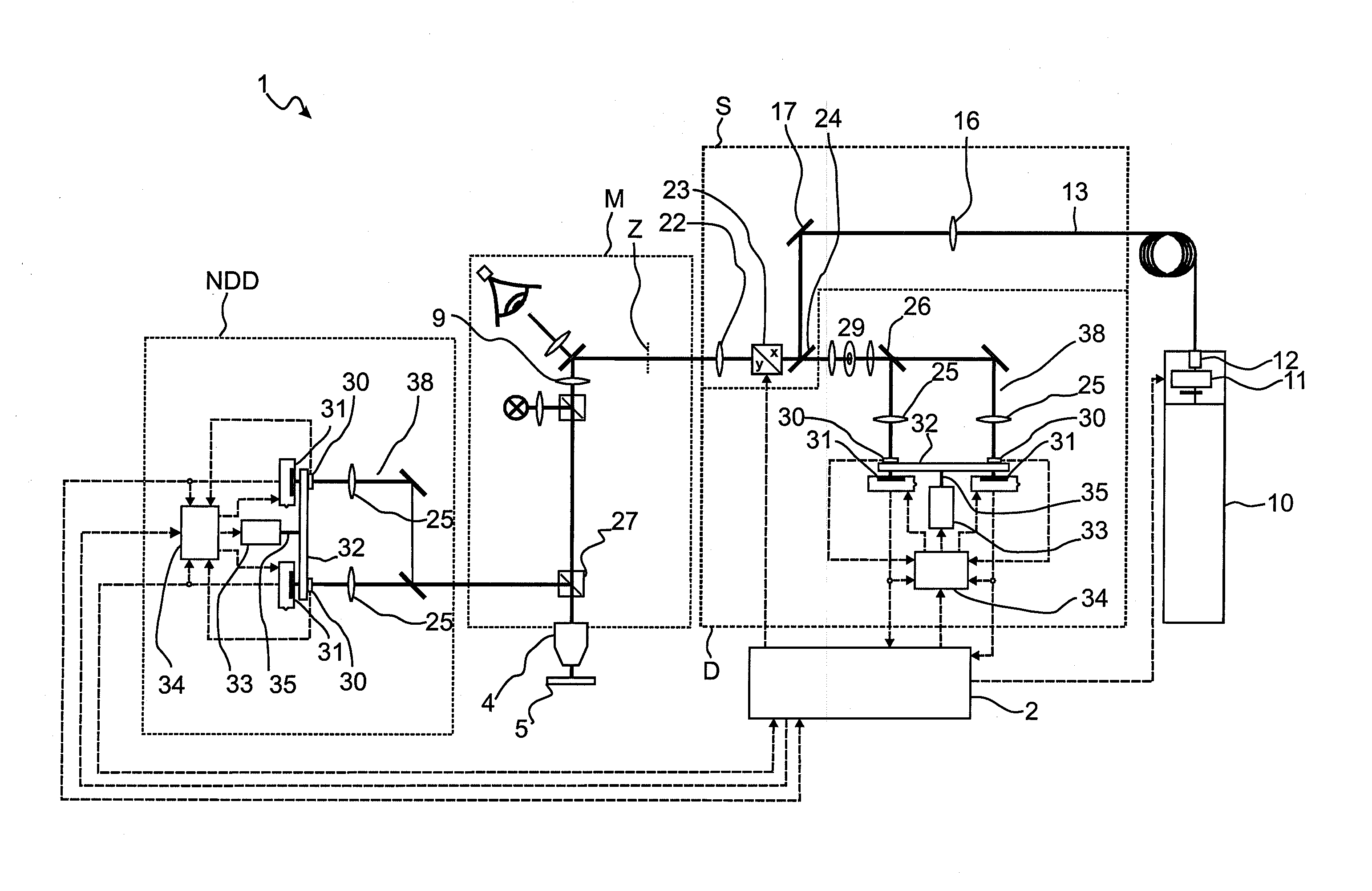
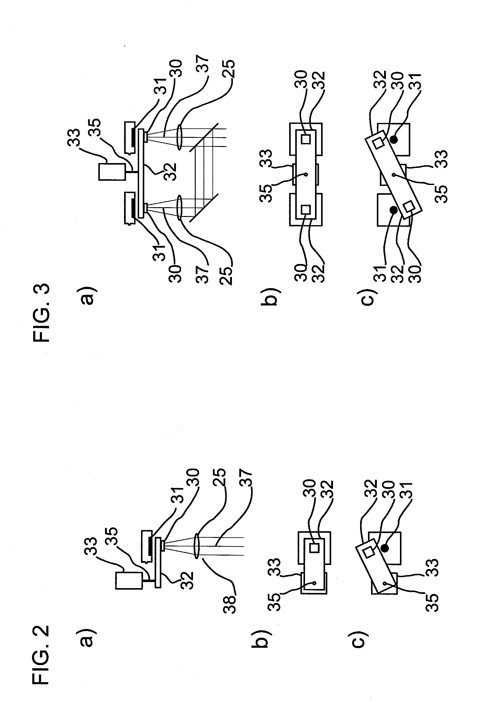
[0015]Optics which focus light on the detector are preferably provided for the detection of low light outputs. The shutter is designed in such a way that the monitor diode is located in, or in the vicinity of, a focus of the light when the detection beam path is closed. The active surface of the monitor diode then advantageously collects all of the light arriving at this point in order to achieve the best possible signal-to-noise ratio. In this way, the monitor diode can also detect low light outputs.
[0019]In another preferred embodiment form, the shutter is rotatable around an axis which is oriented substantially perpendicular to the optical axis of the beam path. This arrangement is particularly space-saving. This is especially true when there is no space available at the sides of the detectors for installing the shutter and its movement mechanism.
[0020]The movement of the closing flap can be carried out, for example, by means of magnetic switches or electric motors. It may be advantageous to de-energize the motor when measurements are being carried out by the detectors so as not to disturb the sensitive detectors. In order to maintain its position when the motor is de-energized, the shutter can be provided with a catch (e.g., spring catch, magnetic holder, or the like). If it is not possible for reasons of space to connect the motor directly to the closing flap, a coupling can also be carried out, for example, by a belt drive or lever.

Problems solved by technology

However, in an arrangement of this kind excessive light output cannot be prevented from striking the detector after opening the detection beam path because the shutter is controlled independently from the light output and this light output can only be measured by the detector after the shutter is opened.
The arrangement described in DE 10253609A1 has some drawbacks, particularly when low light outputs must be detected.
Therefore, the detecting efficiency of the microscope is reduced.
Also, the use of acousto-optical or electro-optical components and liquid crystal elements as shutters is disadvantageous because they can likewise lead to an attenuation of the light output to be detected and are more cost-intensive than mechanical solutions.

Method used


Image

  • Microscope
  • Microscope
  • Microscope

Examples


Embodiment Construction

[0030]It is to be understood that the figures and descriptions of the present invention have been simplified to illustrate elements that are relevant for a clear understanding of the present invention, while eliminating, for purposes of clarity, many other elements which are conventional in this art. Those of ordinary skill in the art will recognize that other elements are desirable for implementing the present invention. However, because such elements are well known in the art, and because they do not facilitate a better understanding of the present invention, a discussion of such elements is not provided herein.

[0031]The present invention will now be described in detail on the basis of exemplary embodiments.

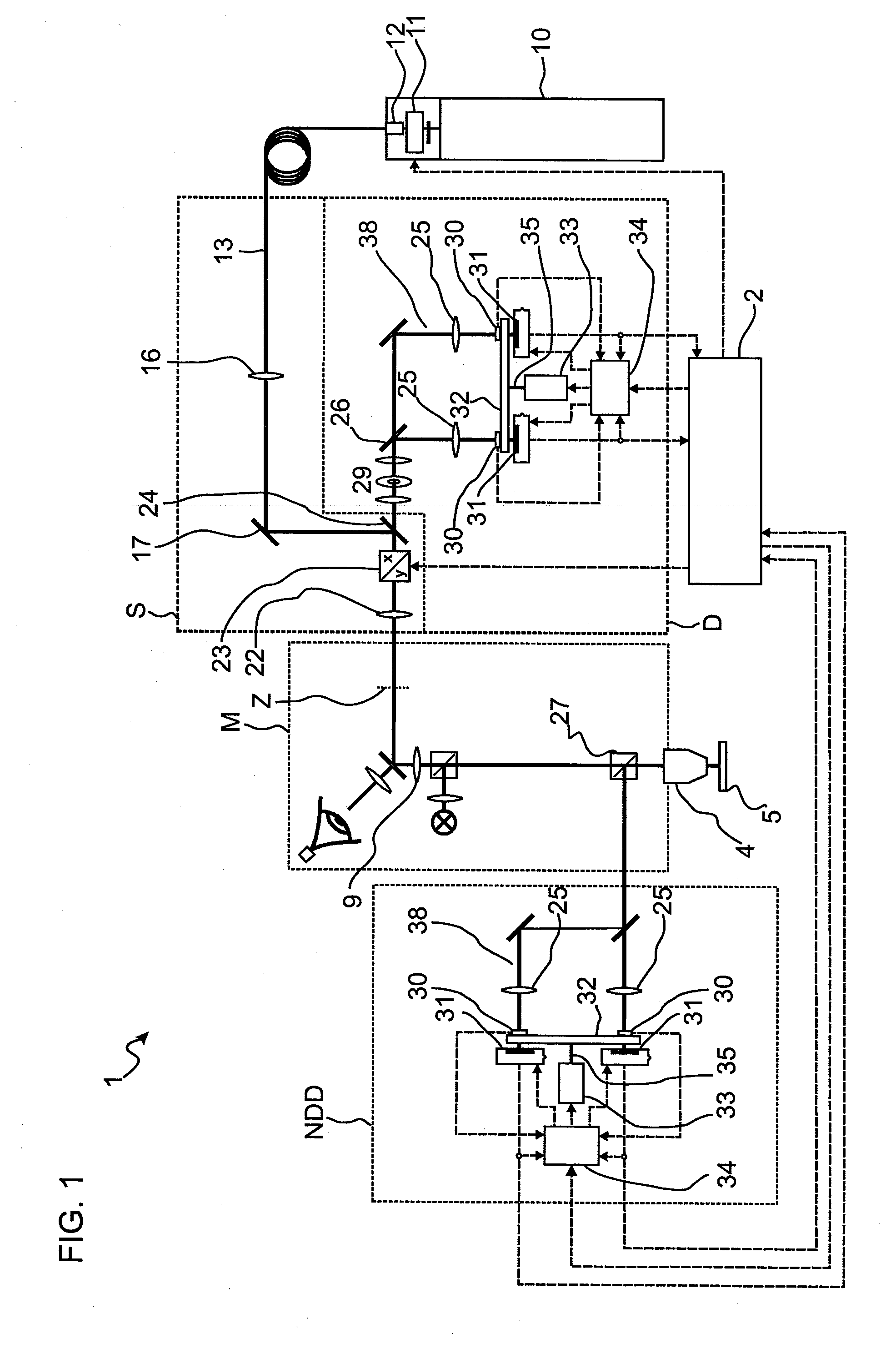
[0032]FIG. 1 shows a schematic diagram of a microscope 1 in the form of a laser scanning microscope. It comprises a microscope unit M and a scan unit S having a common optical interface via an intermediate imaging Z and further comprises a detection unit for descanned detection...


PUM


Abstract

In microscopes, particularly laser scanning microscopes, for detecting light coming from a sample, it is known to protect detectors from excessively high light outputs by means of shutters in the detection beam path. Further, in order to measure the light output impinging on the detector when the detection beam path is closed, a portion of the light is coupled out of the detection beam path and directed to a monitor diode. Constructions of this kind are complicated and costly. In the microscope according to the invention, a monitor diode is arranged on the shutter in such a way that the monitor diode is situated in the detection beam path when the shutter is closed. This makes it possible in a simple manner to measure the light output in a microscope when the detection beam path is closed even without additionally coupling light out of the detection beam path.

Description

[0001]The present application claims priority from German Patent Application No. DE 10 2009 050 020.0 filed on Oct. 16, 2009, the disclosure of which is incorporated herein by reference in its entirety.BACKGROUND OF THE INVENTION[0002]1. Field of the Invention[0003]The invention is directed to a microscope, preferably a laser scanning microscope, with at least one detector for detecting sample light coming from a sample, wherein the detector is protected from excessively high light outputs by at least one shutter.[0004]2. Description of Related Art[0005]Microscopes of the type mentioned above generally have detectors, for example, but not exclusively, CCD sensors, photomultiplier tubes (PMTs) or avalanche photo diodes (APDs) for detecting sample light such as, for example, fluorescent light. Particularly when using detectors designed for detecting very low light outputs or when light outputs in excess of the dynamic range of the detectors can occur, shutters are often arranged in fr...

Claims


Application Information

Patent Timeline
IPC IPC(8): G02B21/06
CPCG02B21/008G02B21/0044
Inventor KUEHN, PETERSCHMIDT, DIETMARMEHNER, THOMAS
Owner CARL ZEISS MICROSCOPY GMBH
Learn More