MRAM having memory cell array in which cross-point memory cells are arranged by hierarchical bit line scheme and data read method thereof

a memory cell array and data read technology, applied in the field of memory cell arrays, can solve the problems of insufficient practical utility, difficult to increase capacity or the degree of integration, and the difficulty of ensuring the read margin

Inactive Publication Date: 2005-05-10
KK TOSHIBA
View PDF1 Cites 37 Cited by
  • Summary
  • Abstract
  • Description
  • Claims
  • Application Information

AI Technical Summary

Benefits of technology

[0014]According to still another aspect of the invention, there is provided a magnetic random access memory comprising a memory cell array of hierarchical bit line scheme in which cross-point memory cells that exhibit a magnetoresistive effect are laid out in a matrix, and a read bit line to be used in a data read mode is constituted by a main bit line and a sub bit line, connection means for selectively connecting a word line connected to a cross-point memory cell to be selected to one of first and second potential supply sources which are different from each other, and control means for controlling the connection means to selectively connect the word line and to set a further word line in an electrically floating state, wherein the control means comprises first and second row decoders and word line drivers to set a potential of the word line in the read mode, and when the connection means is deactivated by the first and second row decoders and word line drivers, the further word line is set in the electrically floating state.

Problems solved by technology

How to ensure the read margin presents a significant challenge in implementing MRAMs.
The practical utility is believed to be still insufficient at present.
Hence, it is difficult to increase the capacity or the degree of integration.

Method used


Image

  • MRAM having memory cell array in which cross-point memory cells are arranged by hierarchical bit line scheme and data read method thereof
  • MRAM having memory cell array in which cross-point memory cells are arranged by hierarchical bit line scheme and data read method thereof
  • MRAM having memory cell array in which cross-point memory cells are arranged by hierarchical bit line scheme and data read method thereof

Examples


first embodiment

[First Embodiment]

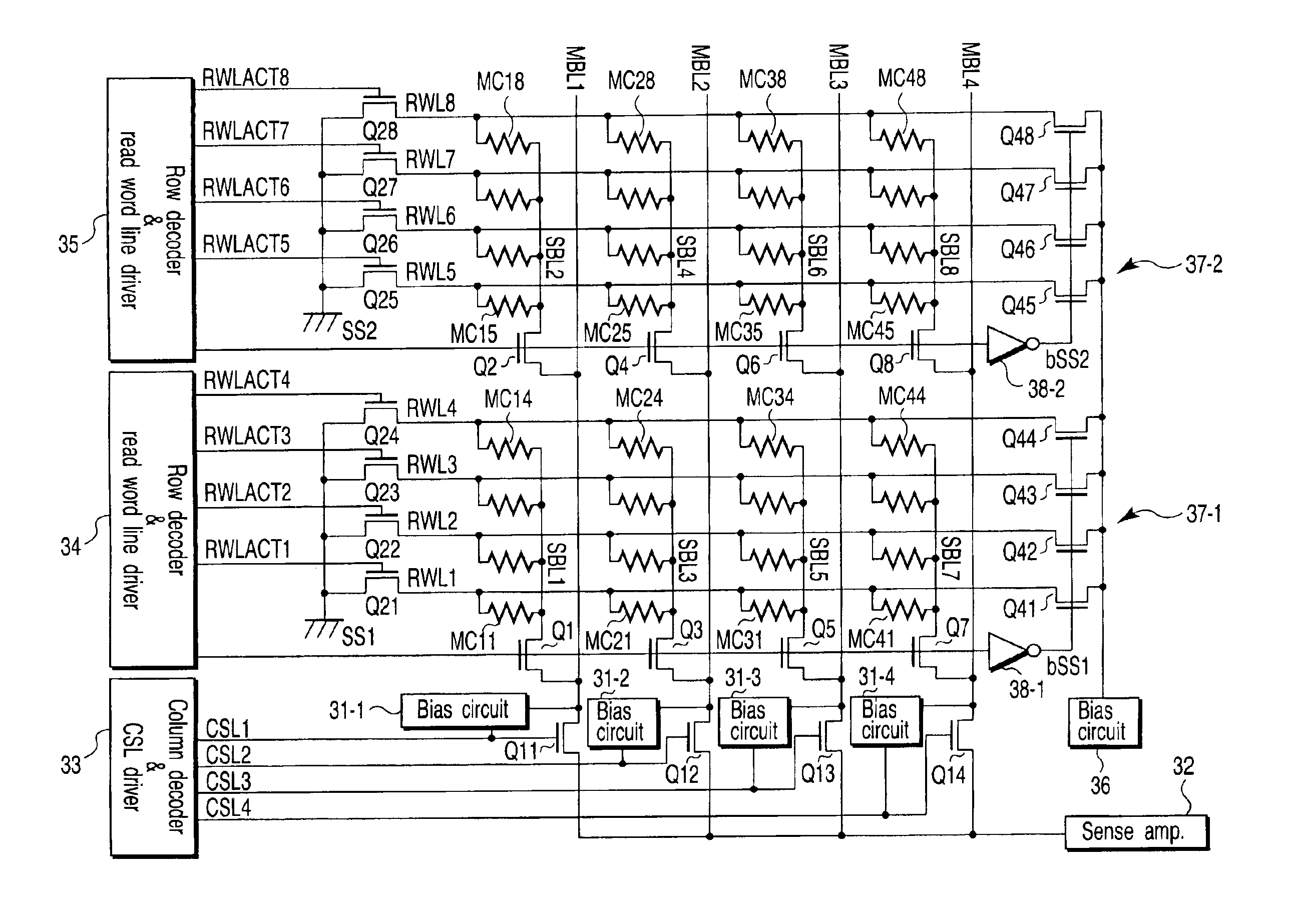
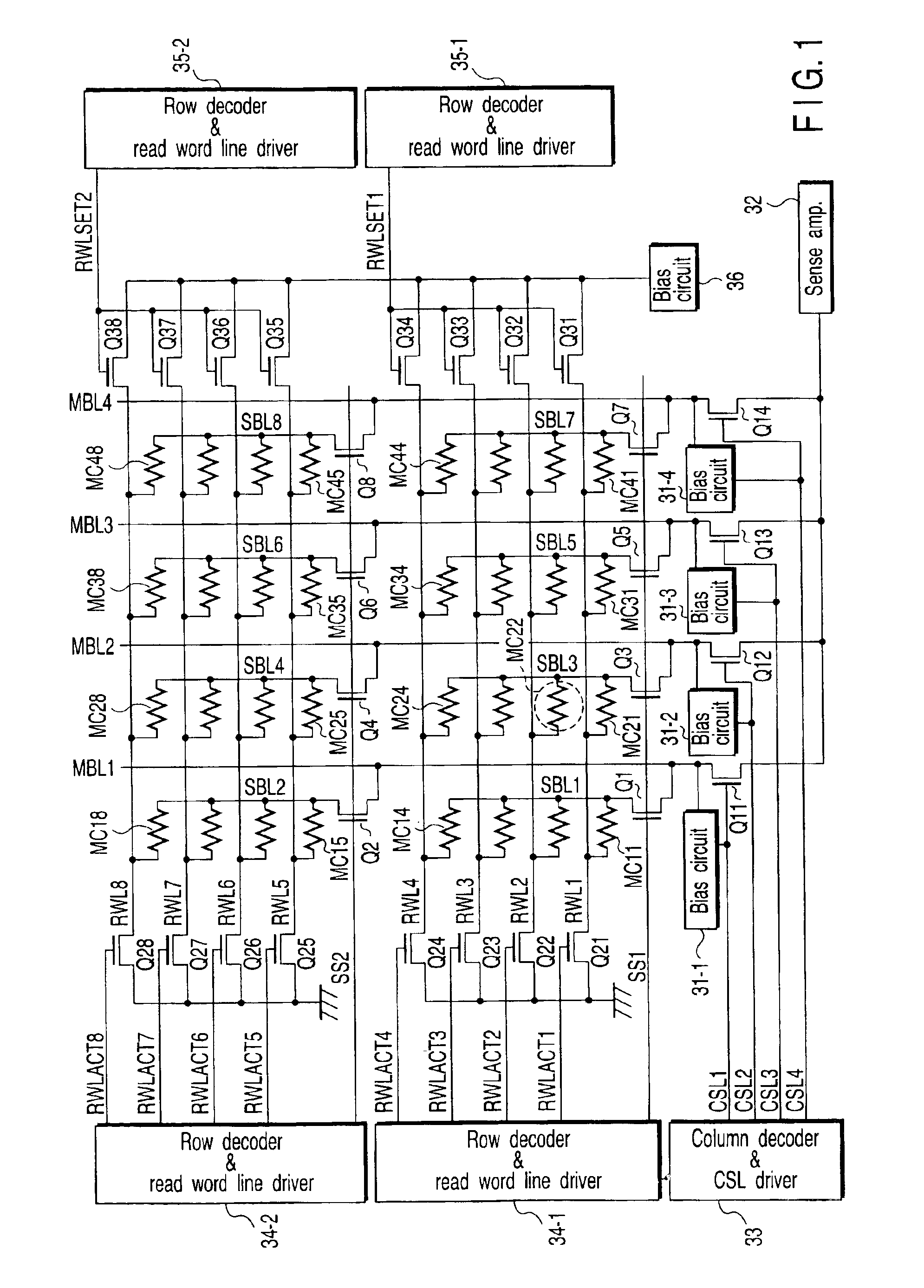
[0031]FIG. 1 is a block diagram showing the main part of a magnetic random access memory (MRAM) according to the first embodiment of the present invention. The present invention is related to a read operation. For the sake of simplicity, FIG. 1 shows the core portion of the read system and does not illustrate the core portion of the write system. Cross-point memory cells MC11 to MC48 each constructed by an MTJ element are arranged in a plurality of (two) memory cell blocks (cell units). One terminal of each to cross-point memory cells MC11 to MC14, MC21 to MC24, MC31 to MC34, and MC41 to MC44 in the first memory cell block is connected by fours to a corresponding one of sub bit lines SBL1, SBL3, SBL5, and SBL7 serving as common nodes. One terminal of each cross-point memory cells MC15 to MC18, MC25 to MC28, MC35 to MC38, and MC45 to MC48 in the second memory cell block is connected by fours to a corresponding one of sub bit lines SBL2, SBL4, SBL6, and SBL8 serving ...

second embodiment

[Second Embodiment]

[0047]FIG. 3 is a block diagram showing the schematic structure of an MRAM according to the second embodiment of the present invention. The same reference numerals as in FIG. 1 denote the same parts in FIG. 3, and a detailed description thereof will be omitted. The second embodiment is different from the first embodiment in that a row decoder & read word line driver is arranged only at one end of each of read word lines RWL1 to RWL8, though the row decoders & read word line drivers are arranged at two ends in FIG. 1.

[0048]To implement this circuit scheme, selection circuits 37-1 and 37-2 which selectively select the read word lines RWL1 to RWL4 and RWL5 to RWL8 to a bias circuit 36 for each cell unit are arranged. The selection circuit 37-1 is constituted by NMOS transistors Q41 to Q44 each of which has a current path having one end connected to a corresponding one of the read word lines RWL1 to RWL4 and the other end commonly connected to the output terminal of t...

third embodiment

[Third Embodiment]

[0051]FIG. 5 is a block diagram showing the schematic structure of an MRAM according to the third embodiment of the present invention. In the third embodiment, a row decoder & read word line driver is arranged only at one end of each of read word lines RWL1 to RWL8, as in FIG. 3, though the row decoders & read word line drivers are arranged at two ends in FIG. 1. Selection circuits 39-1 and 39-2 are formed from PMOS transistors Q51 to Q54 and Q55 to Q58 to directly supply gate signals (signals that are transferred through select lines SS1 and SS2 to selectively connect sub bit lines to main bit lines) to the MOS transistors Q51 to Q54 and Q55 to Q58.

[0052]FIG. 6 is an operation timing chart in the third embodiment. The basic operation is the same as in the first and second embodiments except that the gate signals (the potentials of the select lines SS1 and SS2) are used for the operation of selectively connecting the read word lines RWL1 to RWL4 and RWL5 to RWL8 to...


PUM


Abstract

A memory cell array is of a hierarchical bit line scheme in which cross-point memory cells that exhibit a magnetoresistive effect are laid out in a matrix, and a read bit line to be used in a data read mode is constituted by a main bit line and a sub bit line. A column select circuit selects a main bit line and connects it to a sense amplifier. A row select circuit selects a word line for each cell unit, and in read operation, sets, in a floating state, word lines to which unselected memory cells connected to the sub bit line to which a selected memory cell is connected are connected, and sets the remaining word lines connected to sub bit lines which do not include the selected memory cell to a potential substantially equal to the main bit line.

Description

CROSS-REFERENCE TO RELATED APPLICATIONS[0001]This application is based upon and claims the benefit of priority from the prior Japanese Patent Application No. 2003-144792, filed May 22, 2003, the entire contents of which are incorporated herein by reference.BACKGROUND OF THE INVENTION[0002]1. Field of the Invention[0003]The present invention relates to a magnetic random access memory (MRAM) which stores binary information using the magnetoresistive effect, and a data read method thereof and, more particularly, to potential control of main / sub bit lines and word lines in the read mode of a memory cell array in which cross-point memory cells are arranged by a divided bit line structure (hierarchical bit line scheme).[0004]2. Description of the Related Art[0005]MRAMs are devices which perform memory operation by storing binary information using the magnetoresistive effect. They are regarded as one of candidates for universal storage devices that can realize all the nonvolatility, high i...

Claims


Application Information

Patent Timeline
Patent Type & Authority Patents(United States)
IPC IPC(8): G11C11/15G11C7/00G11C7/18G11C11/16G11C11/02
CPCG11C7/18G11C11/16G11C11/15G11C5/063G11C8/08G11C8/10G11C11/1653G11C11/1673
Inventor TSUCHIDA, KENJIIWATA, YOSHIHISAHIGASHI, TOMOKI
Owner KK TOSHIBA
Why Eureka
Try Eureka