
Nutating single cone drill bit

Active Publication Date: 2005-05-17
TIGER 19 PARTNERS
View PDF4 Cites 12 Cited by
  • Summary
  • Abstract
  • Description
  • Claims
  • Application Information

AI Technical Summary

Benefits of technology

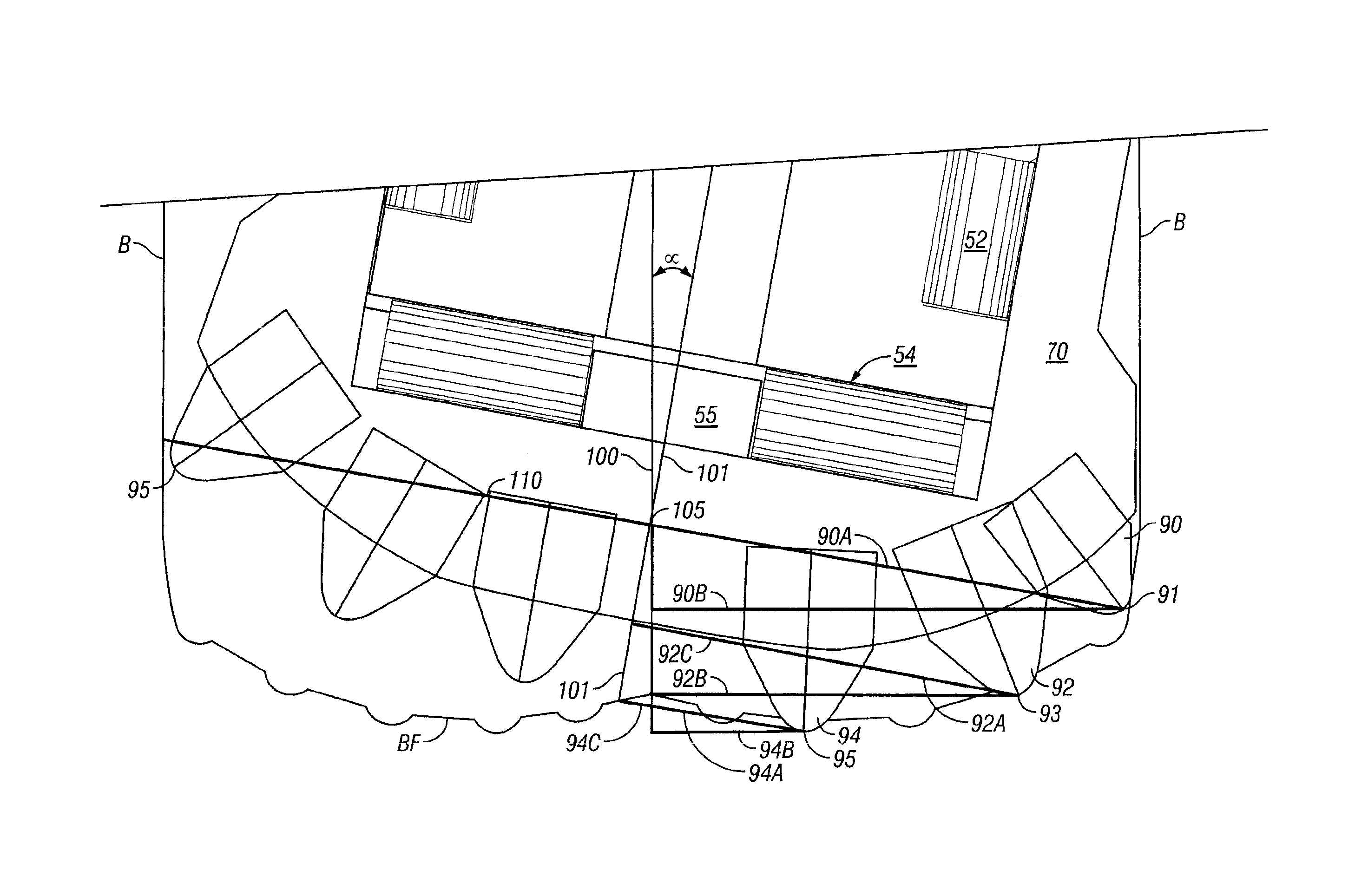
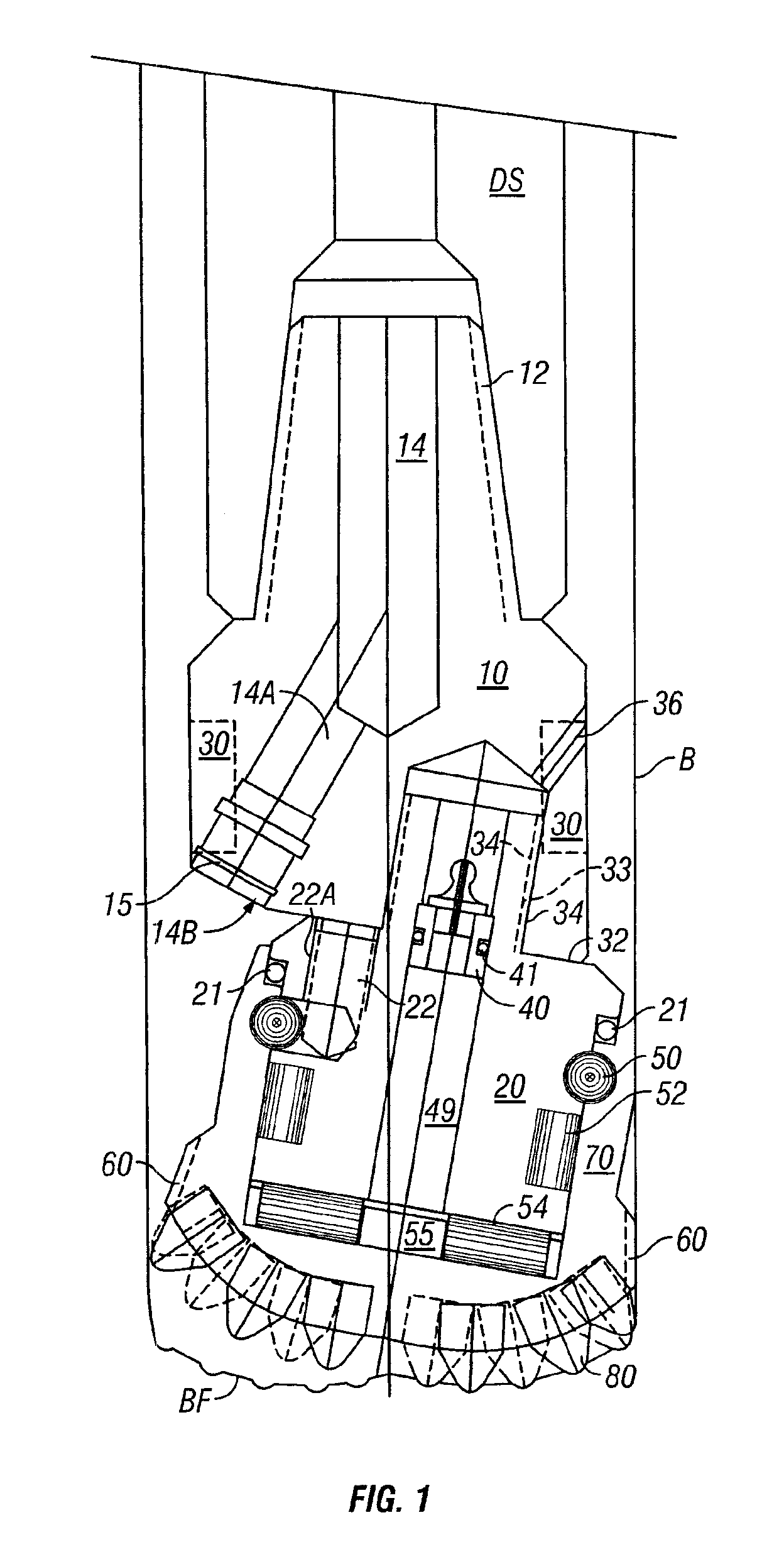
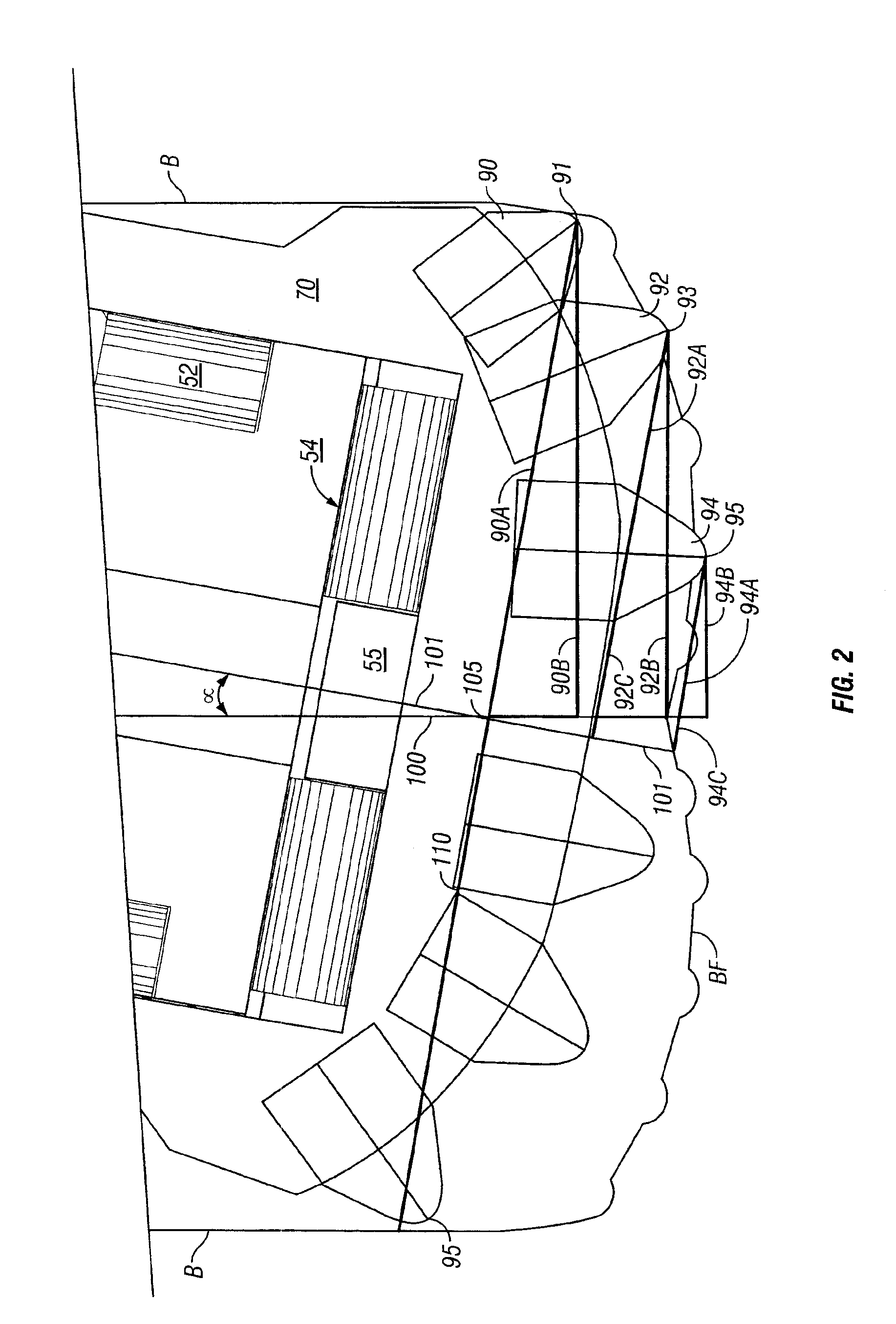
[0005]The present single cone drill bit provides a nutating single cone drill bit having a bit shank to connect to a drill string and providing an eccentric, skewed threaded bore; a threaded journal for engagement in the eccentric, skewed threaded bore of the bit shank; a cutter body rotatably carried on said journal; and a plurality of cutter elements affixed to an exterior peripheral side of said cutter body so that a tip of each cutter element is forward an intersection of a central axis of the drill bit body and an axis of rotation of the cutter body and a first chordal distance to the tip of each cutter element from an axis of cutter rotation is longer than a second chordal distance to said tip of each cutter element from an axis of the bit body rotation. The rolling nutating action of the present bit lifts the opposing cutter buttons off the face of the borehole while the cutters directly at the borehole face engage the rock to be crushed or cut. The skewed angle of the cutter body as it rotates prevents the non-cutting elements from dragging across the opposing face and thereby reduces the wear experienced by the bit overall.
[0006]Since the present invention offers low resistance to the rotational movement of the drill string, it provides a much lower operating torque and may be used with much smaller drilling rigs such as those used by utility contractors for drilling purposes. The low torque of this drill bit also lowers the cost of power used for a normal drilling program.

Problems solved by technology

Previous, single cone drill bits however provided substantial scraping of the cutter elements causing abnormal wear and torque on the drill string assembly.
Each of the prior single cone drill bits were subject to excessive wearing of the cutting elements because at least during some portion of the rotation, the cutter elements were dragged by the circular motion of the bit on the journal across the formation face rather than moved in compressive engagement with the surface.
These cutter elements are designed to have long use lives if used in compression, but having a tendency to break if subjected to side shear or scraping.

Method used


Image

  • Nutating single cone drill bit
  • Nutating single cone drill bit
  • Nutating single cone drill bit

Examples


Embodiment Construction

[0014]The present invention includes a single cone bit having an axis of rotation skewed from the longitudinal axis of the drill string to which it can be attached providing substantial main thrust bearings and providing a cutter shell and cutter elements disposed so that each cutter element tip lies forward intersection of the central axis of the drill bit body and the axis of rotation of the cutter shell so that the chordal distance to the tip of each cutter element from the axis of cutter rotation is always longer than the chordal distance to the tip of each element from the axis of the bit body rotation.

[0015]As shown in FIG. 1, the drill bit is mounted on a drill bit shank 10 which provides threaded connections 12 for connection to a drill string, drill motor or other bottom hole assembly (shown schematically as DS) in a manner well known to those in the drilling industry. The drill bit shank 10 also provides a longitudinal passage 14 to allow fluid communication of drilling fl...


PUM


Abstract

A nutating single cone drill bit includes a bit shank defining a bit axis, a journal defining a rotation axis skewed from the bit axis, and a cutter elements mounted upon a cutter body wherein the tip of each cutter elements is forward a plane defined normal to the cutter axis at an intersection of the cutter axis with the bit axis.

Description

CROSS REFERENCE TO RELATED APPLICATIONS[0001]This application claims the benefit of U.S. Provisional Patent Application Ser. No. 60 / 320,106 filed on Apr. 14, 2003, by Allen Kent Rives, hereby incorporated herein by reference.BACKGROUND OF INVENTION[0002]The present invention generally relates to drill bits for boring subterranean and sub sea formations. More particularly, the present invention relates to a nutating single cone drill bit having a skewed axis of rotation to the central axis of the bit body in the borehole providing low torque and allowing high compressive loading on the bit assembly.[0003]A number of single cone bits have been proposed through the years to drill bore holes for mining, oil and gas exploration, and utility construction. It has been previously recognized that a single cone bit would offer superior design characteristics, such as bearing size permitting greater longitudinal compressive loading on the drill bit. Previous, single cone drill bits however pro...

Claims


Application Information

Patent Timeline
IPC IPC(8): E21B10/08E21B10/22
CPCE21B10/22E21B10/083E21B7/26E21B11/02
Inventor RIVES, ALLEN KENT
Owner TIGER 19 PARTNERS
Learn More