Method for separating analyte from a sample

a technology of analyte and sample, applied in the field of method for separating analyte from a sample, can solve the problems of complex fluidic assembly processing algorithms, limited volume of fluid sample which can be processed, and complex contemporary biomedical processing instruments. achieve the effect of increasing the elution efficiency

Inactive Publication Date: 2005-05-17
CEPHEID INC
View PDF123 Cites 378 Cited by
  • Summary
  • Abstract
  • Description
  • Claims
  • Application Information

AI Technical Summary

Benefits of technology

[0013]A flow path for carrying elution fluid is also formed in the cartridge. The elution flow path passes through the flow-through component, thereby releasing captured analyte from the component into the elution fluid. The elution flow path diverges from the sample flow path after passing through the component. In the preferred embodiment, the cartridge also includes, or may be coupled to, a heating element for heating the component, thereby increasing elution efficiency.

Problems solved by technology

Whether incorporated into a bench-top instrument, a disposable cartridge, or a combination of the two, such processing involves complex fluidic assemblies and processing algorithms.
Contemporary biomedical processing instruments are typically complex, robotically operated devices that move boluses of liquids automatically from one processing region to another.
While the bolus approach allows for the implementation of complex processing methods, the volume of the fluid sample which can be processed is limited by the size of the individual processing regions, especially where the sample is transiently processed.
Thus, the lowest detectable concentration of analyte, i.e. sensitivity, in any assay based on a bolus approach is also limited.
Such a large chip would not only be expensive, but would also defeat the purpose of miniaturization, especially for many types of disposable medical or environmental diagnostic uses.
These small volumes are not practical for many realistic diagnostic applications.

Method used


Image

  • Method for separating analyte from a sample
  • Method for separating analyte from a sample
  • Method for separating analyte from a sample

Examples


Embodiment Construction

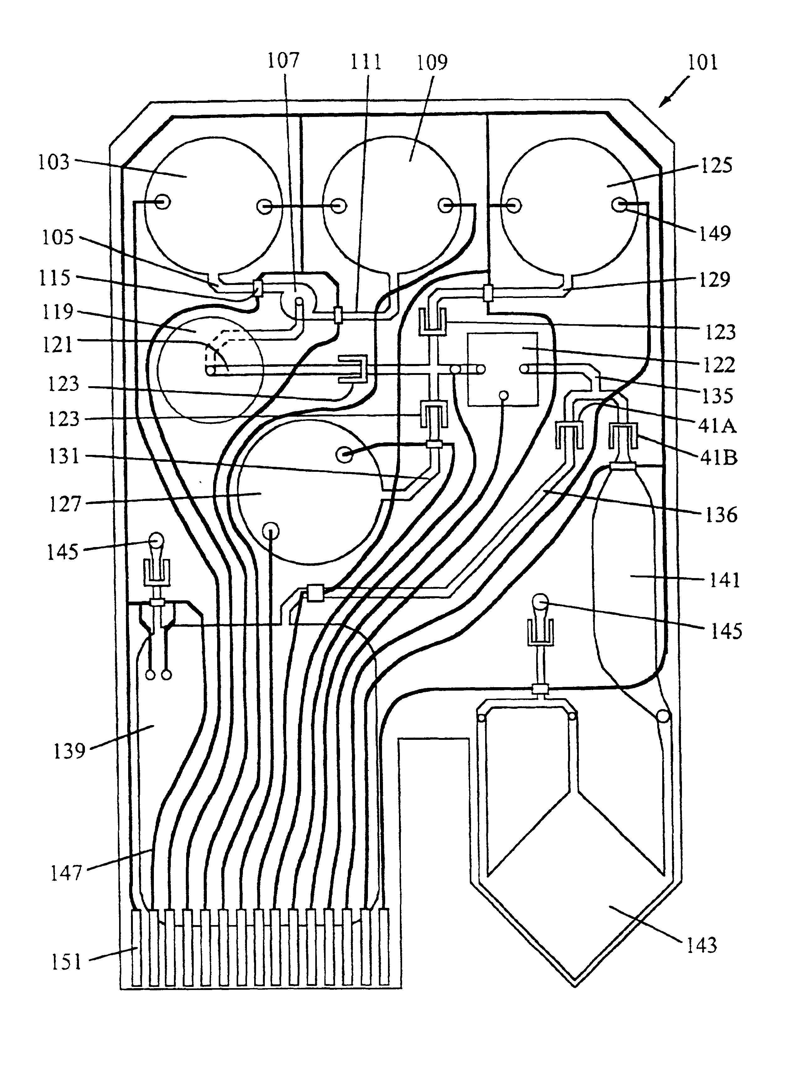
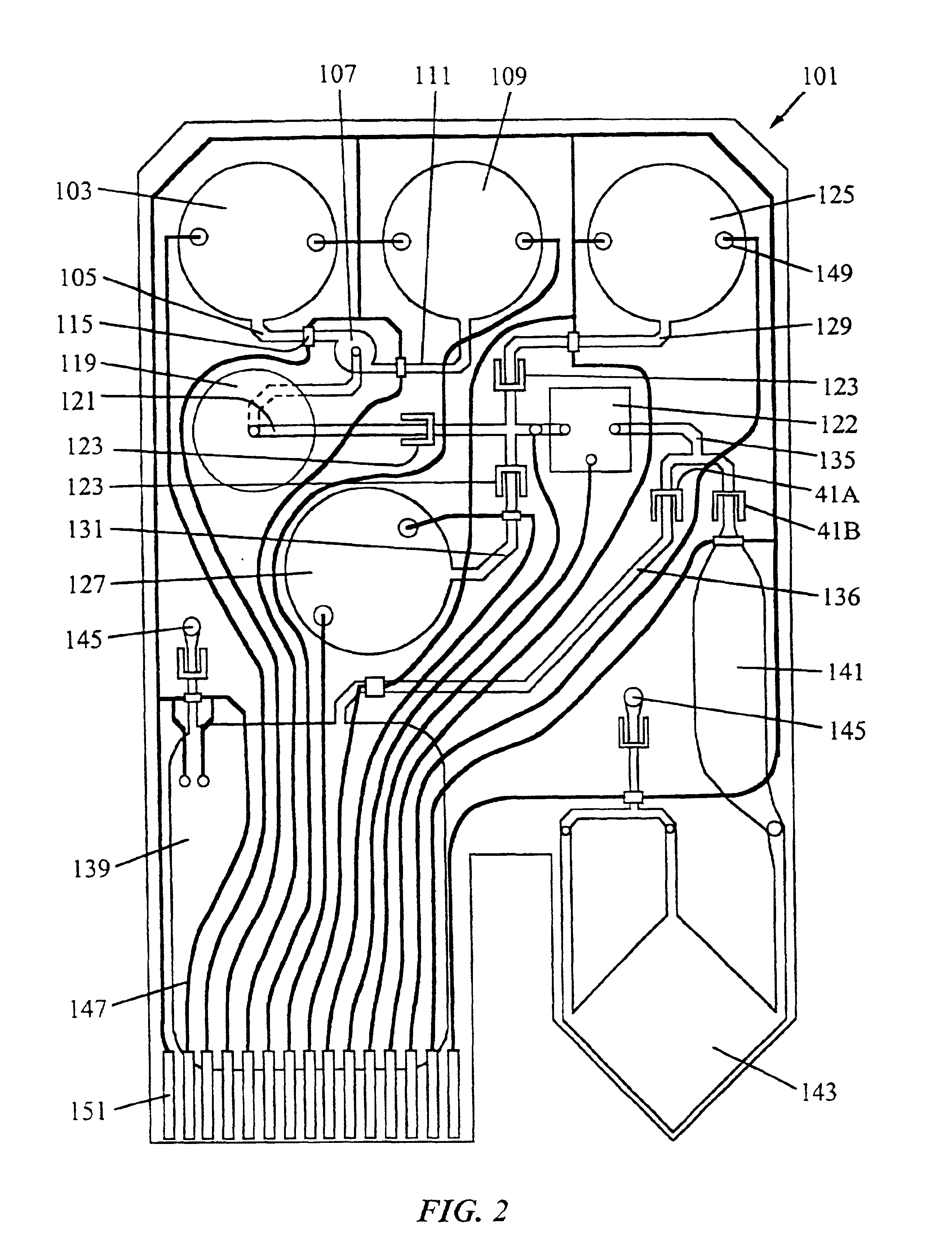
[0040]The cartridges of the present invention allow for significantly improved processing of a fluid sample for the detection and / or analysis of chemical components in the sample, such as biological molecules. The cartridges may also be designed to automatically conduct processes, such as mixing reagents with the fluid sample, lysing, filtering, and introducing the mixture into a reaction chamber or separate reaction vessel appropriate for further processing, e.g., detection or amplification of the analyte.

[0041]Since the operations on the fluid sample are performed on the sample stream as it flows through the various regions of the cartridge, any incorporated microfluidic processing chip or other component can be very small, as much as one hundred times smaller than with the bolus-oriented approach. This allows the entire processing facility to be small, yet capable of processing relatively large fluid samples (e.g., 0.1 to 10 mL), and thus to take advantage of the unique propertie...


PUM

PropertyMeasurementUnit
volumeaaaaaaaaaa
volumeaaaaaaaaaa
flow rateaaaaaaaaaa

Abstract

An analyte is separated from a fluid sample by introducing the sample into a cartridge having an extraction chamber containing capture material for capturing the analyte. The sample is forced to flow through the extraction chamber to capture the analyte with the capture material in the extraction chamber. The captured analyte is then eluted from the extraction chamber by forcing an elution fluid to flow through the extraction chamber. The cartridge may optionally include a lysing region for lysing sample components (e.g., cells spores, or microorganisms), a waste chamber for storing waste fluid, and reaction or detection chambers for chemically reacting or detecting the eluted analyte.

Description

PARENT APPLICATION DATA[0001]The application is a division of U.S. application Ser. No. 09 / 331,911, filed Jun. 25, 1999, now U.S. Pat. No. 6,440,725, which is a 371 of International Application PCT / US98 / 27632, filed Dec. 24, 1998, which international application is a continuation-in-part of U.S. Ser. No. 08 / 998,188, filed Dec. 24, 1997, now abandoned and is a continuation-in-part of U.S. Ser. No. 09 / 115,454, file Jul. 14, 1998, now abandoned, which is a continuation-in-part of U.S. Ser. No. 08 / 910,434, filed Aug. 13, 1997, now U.S. Pat. No. 6,368,871. All of these applications are incorporated by reference herein for all purposes.FIELD OF THE INVENTION[0002]This invention relates to a method for separating an analyte from a sample.BACKGROUND OF THE INVENTION[0003]The analysis of clinical or environmental fluids generally involves a series of chemical, optical, electrical, mechanical, or thermal processing steps on the fluid samples. Whether incorporated into a bench-top instrument, ...

Claims


Application Information

Patent Timeline
Patent Type & Authority Patents(United States)
IPC IPC(8): C12M1/33G01N31/20B01D11/00B01J19/00B01L3/00B01L7/00C12M1/00C12M1/26C12M1/34C40B60/14G01N1/28G01N30/60G01N33/50G01N35/08G01N37/00
CPCB01L3/502715B01L3/502753G01N30/6091G01N30/6095C12M47/06B01J2219/00432Y10T436/25375B01L7/52B01L2200/0621B01L2200/0631B01L2200/0636B01L2200/10B01L2300/0816B01L2300/1827B01L2400/0421B01L2400/046B01L2400/0487B01L2400/0622B01L2400/0644B01L2400/086C40B60/14Y10T436/255B01J2219/00529B01L2300/0883G01F1/708C12M47/02
Inventor PETERSEN, KURT E.MCMILLAN, WILLIAM A.CHRISTEL, LEE A.CHANG, RONALDPOURAHMADI, FARZADCHING, JESUSKOVACS, GREGORY T. A.NORTHRUP, M. ALLEN
Owner CEPHEID INC
Why Eureka
Try Eureka